command (in CADprofi
program) or the Couple cable trays
command (in CADprofi
program) or the Couple cable trays  command (in CADprofi OEM program)
are used.
command (in CADprofi OEM program)
are used.In CADprofi program it is possible to draw mesh trays.
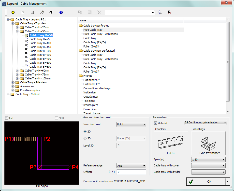
These systems are available by the Products library command, e.g. in the manufacturer libraries Legrand CabloCAD, TkRem etc.
For more convenient edition of
trays with automatic insertion of elbows and tees the Join general
elements command (in CADprofi
program) or the Couple cable trays command (in CADprofi OEM program)
are used.
|
|
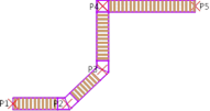
During the drawing of strings, program automatically inserts elbows and trays in accordance with points indicated by the user. By setting the reference edge and offset it’s possible to draw strings for example along the walls. |
|
|
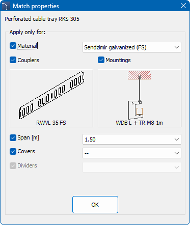
Use the Match cable tray properties  command to select the right
accessories for the selected trays.
command to select the right
accessories for the selected trays.
|
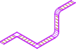
•Draw strings in the XY plane of any level, which can be specified in the dialog window (Level 3D edit box). •Use the command for automatic connection, which requires that both joined elements must be on the same XY plane (their level must be the same). •Attach elements with the one-click method. It is possible in every case, regardless of the position of the object. |
|
For automatic insertion of diagrams of mounting pieces, you can use the Insert: 2D/3D, Symbols, Descriptions….
Connecting pieces catalogue - In designs created with Legrand CabloCAD, data about connecting pieces is taken into account when drawing trays. Therefore, it is not necessary to insert connecting pieces into the design as graphical objects. In the connecting pieces catalogue, you can only view technical information about Legrand CabloCAD connecting pieces.
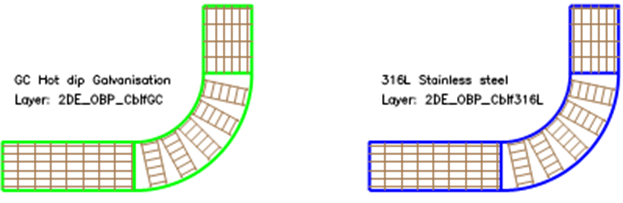
Tray material
During designing it is possible to specify the mesh tray
material. Program inserts trays that are created with different materials on
separate layers.
For example the 2DE_OBP_CblfEZ
layer is used for Cablofil electrolytically
galvanized (EZ), the 2DE_OBP_Cblf316L layer is used for trays made of
stainless steel (316L).
During insertion of Cablofil elements program checks the layer name and includes only elements that lie on layers that begin with the 2DE_OBP_Cblf. Because of that user should not change the trays layer name.
An exception of this rule may be for example a necessity to add additional red layer for anti-fire or other special installations. For example the 2DE_OBP_CblfEZ_ppoz can be used in anti-fire installations for electrolytically galvanized trays. In such case in Cablofil BOMs instead of material, the layer name will be visible.
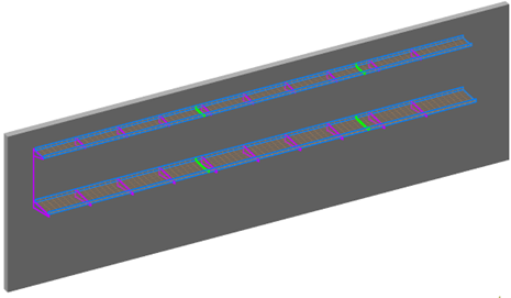
Complex constructions
In real installations it is very often needed to conduct trays one above the other. Sometimes such constructions can consist of many trays that are mounted to the ceiling, walls, etc. On plans it is very difficult to represent such constructions, because many trays that overlap each other, therefore the project becomes unreadable.
This problem is solved by "complex constructions". In this case instead of drawing many trays that overlap, it is possible to draw a route, which shows the trays sequence and a scheme that represents the arrangement of ducts and fittings in the route.
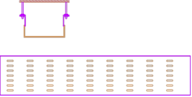
Example: two trays - one above the other
2D drawing - advanced construction
in CabloCAD
Complex construction scheme must contain:
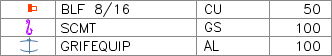
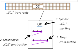
1. Construction marking symbol - marking must be unique (e.g. C01, A15 etc.). In one project it is not possible to define several complex constructions with the same marking (ID).
2. Mounting - scheme that contains special mounting symbols. When inserting mounting symbols the mounting spacing and construction ID must be provided (e.g. C01, A15…).
3. Tray cross-section - when inserting mounting symbols user should also specify the couplers type, thanks to which trays and construction markings are connected (e.g. C01, A15…).
4. Tray route - when drawing a tray route it is necessary to specify its total width and height that is occupied by all trays in the specified route.
Notice:
To a specified complex construction (e.g. C01) belong all elements that contain the specified ID (e.g. C01). For this reason, for visual control, the ID is visible in all mounting symbols and trays cross-section. This ID is on a non-printed layer, that's why it is visible only on the screen.
In a definition of one complex construction (i.e. one design) it should be avoided to mix elements with different IDs. When copying elements between constructions it is necessary to arrange IDs (i.e. construction attribute marking).

|
It is not possible to define several same complex constructions in a project. For this reason schemes with complex construction definition should not be duplicated. This can lead to errors when creating BOMs (duplicated elements in the drawing can duplicate the number of trays and accessories in BOMs). If user needs to duplicate schemes of complex constructions, all copies should be "exploded" or they must have "cleared IDS" (empty marking attribute). These copies won't be included by the program in BOMs). |