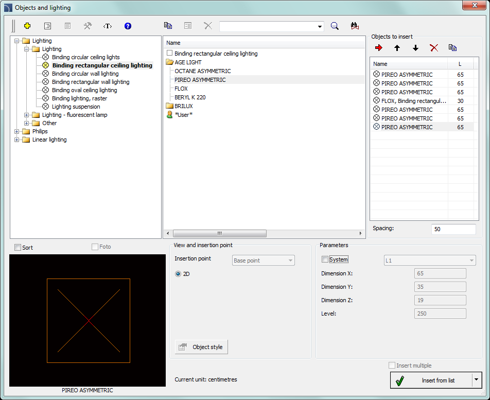
The Objects and lighting command allows to insert typical lighting fixtures. This command also contains sample light fixtures that were prepared on the basis of certain manufacturers catalogs. Before using these lighting fixtures in projects it is advised to check the current offer of these manufacturers.
Lighting fixture is also available in the Symbols - other command. However, it should be noted that symbols are elements that contain only a representation of a specific device and therefore do not need to have the actual dimensions. The Objects and lighting command on the other hand gives the possibility to insert object to the project, whose dimensions match the dimensions of actual devices.

Objects and lighting dialog window
Basic functionality and options regarding symbols are described in the IEC and NFPA Symbols chapter. Additional options for the Objects and lighting command:
Parameters - first element in each category gives the possibility to determine the dimensions. After selecting a such element, user has to specify dimensions in the Dimension X, Y, Z fields.
View and insertion point - for some objects additional views are be available, e.g. side views that allow to insert objects not only on plans but also on cross-sections and other installation views.
6 Procedures
1.
Run the Objects and lighting  command.
2. In the Objects and lighting dialog window expand the needed category.
3. In the detailed list that contains lighting fixture types a list of all available manufacturers or series of types is available.
4. (Optional) Double click on a series of types in order to expand it and display its content.
5. Select an element by clicking a position from the list. If the first element will be chosen, then it will be possible to specify the X, Y and Z dimensions, which allows to insert to the project lighting fixture with non standard dimensions.
6. (Optional) Change the View for the selected element.
7. Disable the System option or select an installation from the available list, to specify the layer for the selected element.
8. Click the OK button to insert the selected object to the drawing.
9. Specify the insertion point and the object rotation angle.
Hint:
If the lighting fixture should be
located on a net, then after inserting the first lighting fixture user can use
the Array (_Array) command from the CAD program.

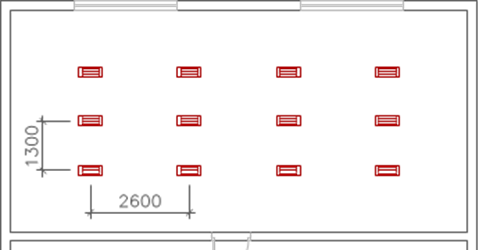
Example of inserting a lighting fixture: After inserting the first lighting fixture, the rest fixtures were copied by using the Array command with the distance 2600 mm x 1300 mm.