 command contains a
library of symbols, objects and markings that are used in transmission networks
and telecommunications drawings.
command contains a
library of symbols, objects and markings that are used in transmission networks
and telecommunications drawings.The Symbols - maps, lines,
pillars command contains a
library of symbols, objects and markings that are used in transmission networks
and telecommunications drawings.
In the Telecommunication category user can find symbols that are used to design copper and fiber networks on maps, as well to create network schemes. Elements that are used in representing the existing, projected and dismantling status are available in the program. Marking symbols are specially designed for the telecommunication branch and allow to quickly describe objects on maps and schemes.
When designing networks, lines that are in the Cable, cable trays - schematic command are also used. Pipe protective casings are available in the 2D Cable trays command.
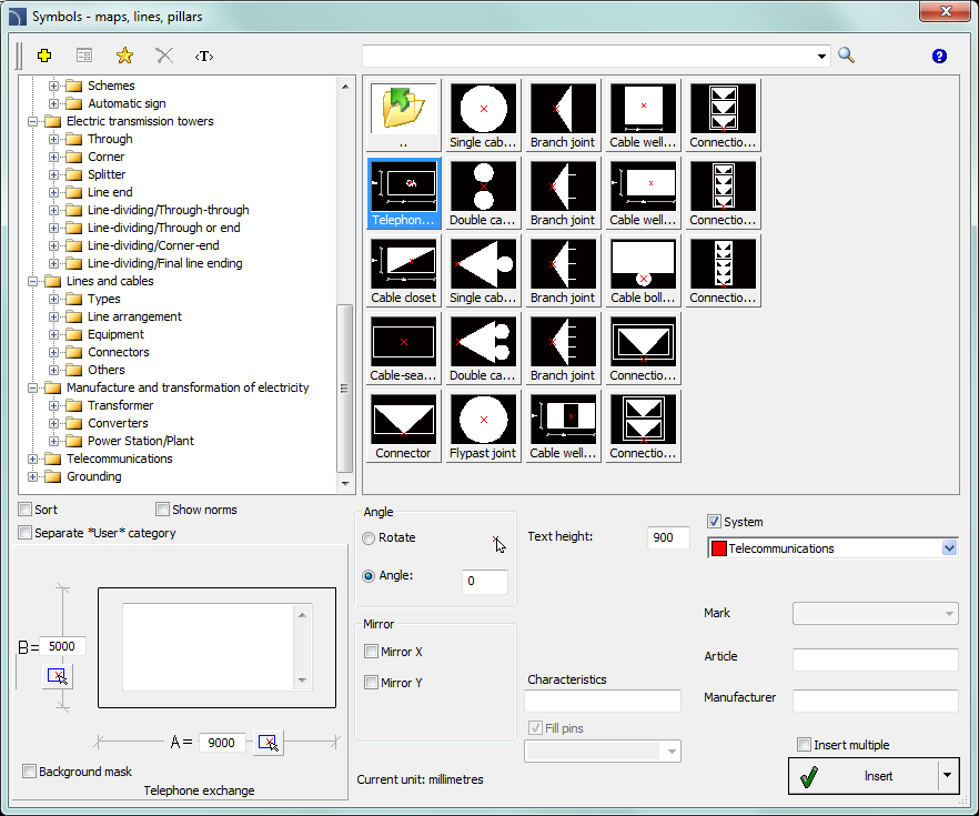
Symbols - maps, lines, pillars dialog window
Basic functionality and all options regarding symbols are described in the IEC and NFPA Symbols chapter.
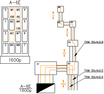
Network scheme example
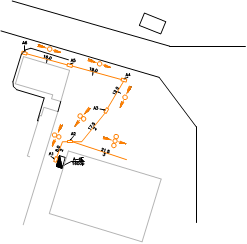
Example of a network scheme on a map