The Descriptions command allows to insert into the project various descriptions that are used in schematic drawings, and in 2D views.
Automatic descriptions
In CADprofi program there are commands that are used to describe and number objects. These commands allow to specify technical and identification parameters, which are later used in creating BOMs and gathering various information about the project. Parameters that are added to the objects can be also used in automatic or semi-automatic drawing descriptions.
Symbols that retrieve information from objects and insert appropriate descriptions are used for that. When inserting automatic descriptions user has to indicate the described object and next specify the description insertion point.
For some symbols it is possible to enable the option to insert them with a leader.
To describe various object user should use appropriate symbols. For example Line type description can be used to describe schematical lines. If user uses this symbol to describe other objects, CADprofi program won't be able to read the needed data. In this case, the symbol will be described incorrectly.
If it's necessary to describe multiple objects, it's convenient to select the Insert multiple option.
Example of automatic descriptions
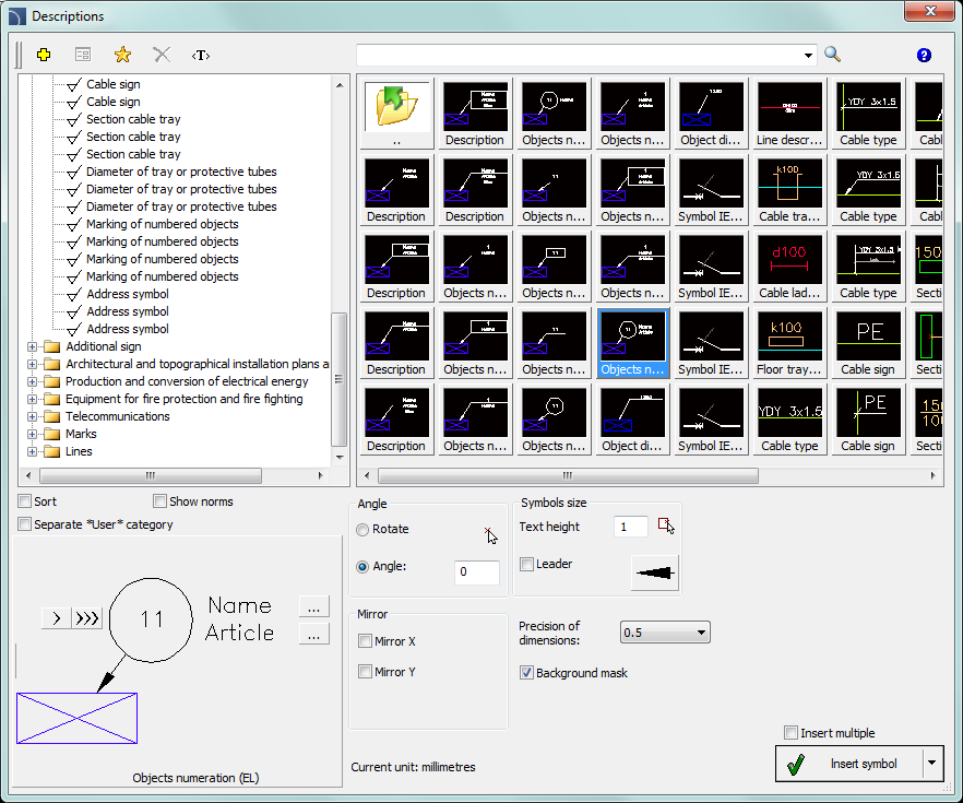
Descriptions dialog window
Basic functionality and options regarding symbols are described in the IEC and NFPA Symbols chapter. Additional options for the Description command:
Text height - specifies
the marks text height and scale. User can enter a value or indicate it from the
drawing  (indicate two points).
Leader -
enables/disables usage of leader for descriptions. By clicking on the  button, that symbolizes the currently set
arrow type, user can change the following leader settings:
button, that symbolizes the currently set
arrow type, user can change the following leader settings:
•Arrow type- symbol that is inserted in the leader starting point for example an arrow.
•Arrow size - determines the leader scale.
•Insert single segment -drawing of a one or multi-segment leader.
Precision of dimensions - defines the precision (decimal number) of all values of dimensions that are placed in marks. These dimensions are automatically retrieved from the indicated object.
Background mask - enables/disables the possibility to mask the symbol background by adding a Wipeout. This feature is helpful if user needs to highlight important information in the drawing.
Multivariant marks and object numbering
Many mark symbols are multivariant symbols, for which user has got a possibility to customize the appearance and to select additional options. For these symbols in the dialog window there are selection fields and text fields buttons available that allow to specify the variant or adoption of symbol to current needs.
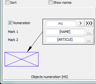
An example of such multivariant symbol is the "Objects numeration" symbol. This symbol can number objects and also retrieve from them required parameters (e.g. name, type etc.). In this way it is possible to quickly number many objects and insert required text in the drawing.
|
CADprofi program automatically detects numbered
objects in the drawing, thanks to which in the dialog window the first
available number |
|
By adding different number prefixes, user can create many numbered sequences (e.g. one F1, F2, F3 sequence for switches and one K1, K2, K3 for relays).
Inserting symbols with the Insert multiple option will cause the symbols to have numbers added to them with increased numeration.
The Mark 1, Mark 2 fields allow to add in the selected symbol any
text or information retrieved from the indicated object. Selecting the
information type will be possible after pressing the  button that is located next to the
field.
button that is located next to the
field.
In the newly opened window user can select the following information:
•Attributes - indicated object attributes values.
•Lines - line type or installation kind.
•Dimensions - dimensions retrieved from the indicated object.
•Others - for example the CAD program system variable values.
6 Procedures
1.
Run the Descriptions  command.
2. In the dialog window select the appropriate description symbol.
3.
(Optional) Change the data type by clicking the Browse  button
and select the data from the list of available data in the Select dialog window.
button
and select the data from the list of available data in the Select dialog window.
4. Specify the parameters: Angle, Mirror and Scale.
5. (Optional) Enable and change Leader settings.
6. Enable/disable the background mask.
7. Enable/disable the Insert multiple option.
8. Click the Insert symbol button, to insert the desired mark into the drawing.
9. Indicate the symbol/object whose data should be inserted into the drawing.
10. Indicate the mark insertion point.
11. (Optional) If the Insert single segment option (in the leader settings) is turned on then indicate a series of points that are segments ends or click the right mouse button to continue.
12. (Optional) Specify the mark rotation angle.
13. (Optional) If in the dialog window the Insert multiple option is enabled then repeat the steps 10-13 in order to insert an additional mark or end the command by clicking the Esc key.
|
|
|
An
example of a description (marking) with number, |
 from the
specific branch (e.g. EL - electrical installations) is being displayed.
The
from the
specific branch (e.g. EL - electrical installations) is being displayed.
The  button allows to select the
next highest number.
button allows to select the
next highest number.