
The PLC controllers command allows to insert to the project any kind of configured blocks of PLC controllers. This command also allows to define any number and type of inputs/outputs, their number and address (numbering).
Block of multivariant controllers are symbols for which it is possible to specify all dimensions and customize their appearance and technical parameters. Basic functionality and all options regarding symbols are described in the Symbols - IEC, NFPA) chapter
When defining a PLC controller block, user should specify its exterior dimensions, and the number of inputs/outputs. After inserting a block, user can describe each inputs/outputs with the help of appropriate signs.
Examples of frequently used controllers configurations, which may be used as a basis in designing user own systems are available in the command.
After inserting the controller into the project it is possible to edit it by using the Edit symbol command.
In the dialog window that is used for defining controllers there are active fields and buttons that allow to freely define various parameters.
Examples of fields and buttons that are used in the dialog window.
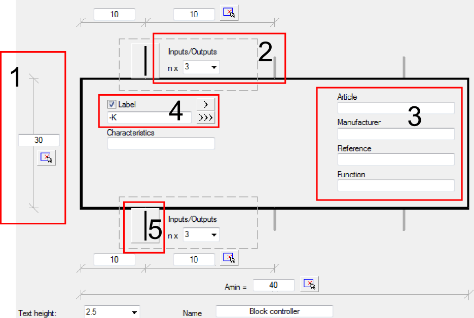
1.
Dimension field – allow to determine the
dimension by entering the value or by indicating two points in the drawing ( button).
2.
Drop-down list – gives the possibility to enter
your own value or to select data from the list by pressing the  button.
3. Text field – gives the possibility to enter any text.
4.
Label – gives the possibility to add subsequent
labels to inserted symbols. Label field is automatically filled with default
marking and the first free number. Thanks to the available buttons, user can
choose between the first free number  and a subsequent number
  . This field can be also filled with any
value.
. This field can be also filled with any
value.
5. Graphical drop-down list – expands the pop-up menu and gives the possibility to choose one of available graphical markings.