The Scheme creator templates
command  allows user to
automatically create power distribution schemes. The work consists of selecting
products from the symbol library and placing them in specific positions on the
matrix in the dialog window. In this way, you can very easily and quickly define
the logical structure of the entire switchgear, focusing only on the selection
of products, rather than manually drawing the scheme.
allows user to
automatically create power distribution schemes. The work consists of selecting
products from the symbol library and placing them in specific positions on the
matrix in the dialog window. In this way, you can very easily and quickly define
the logical structure of the entire switchgear, focusing only on the selection
of products, rather than manually drawing the scheme.
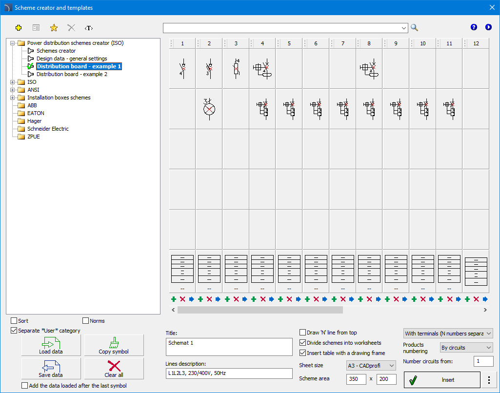
Scheme creator and templates window
The Scheme creator and
templates dialog box contains:
 Insert/Delete Column - inserts an empty circuit
before the specified column of the matrix and allows user to delete the entire
column.
Insert/Delete Column - inserts an empty circuit
before the specified column of the matrix and allows user to delete the entire
column.
 Load data from csv - saves all data from the current
diagram to a csv file.
Load data from csv - saves all data from the current
diagram to a csv file.
 Save data to csv - loads the diagram from a csv
file.
Save data to csv - loads the diagram from a csv
file.
 Copy symbol - activates copy mode. After
selecting the command, click on the cell from which the symbol will be copied to
subsequent cells. To finish, right-click and select Finish copying.
Copy symbol - activates copy mode. After
selecting the command, click on the cell from which the symbol will be copied to
subsequent cells. To finish, right-click and select Finish copying.
 Clear all - deletes all information from the
current scheme.
Clear all - deletes all information from the
current scheme.
Line ‘N’ drawn from the
top - Change the way the ‘N’ potential line is drawn.
Divide diagram into
sheets - enabling this option will divide the inserted scheme into sheets
of the selected size.
Insert with drawing
frame - enables/disables drawing a drawing frame.
Sheet size - specifies
the size of the sheet on which the diagram will be drawn.
Diagram area - allows
user to change the area occupied by the diagram on the sheet.
Number circuits from -
the starting value for circuit numbering.
Scroll buttons
(<<, </>, >>) - buttons that allow user to scroll the view to
the right or left.
|
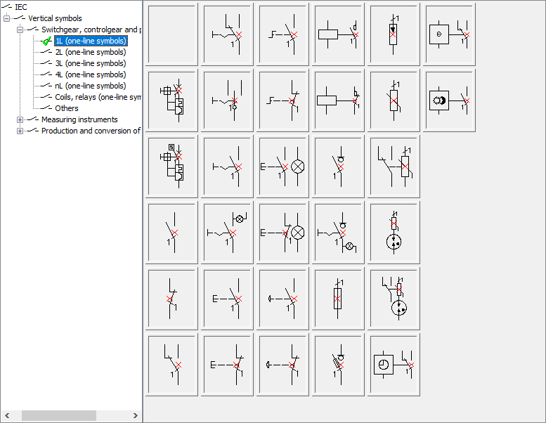
Product selection -
after clicking on the selected cell, a list appears in which user
should indicate the symbol and then select the desired products from the
list. |
|
|
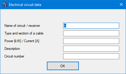
Circuit information -
after clicking on the bottom button of the matrix, user can
enter the name of the circuit (receiver) and additional parameters, such
as: power, current, and type and cross-section of the power cable. |

|
Project data - general settings
This command allows user to specify the data to be included
on the project title page, including: project subject, investor information,
comments, description, etc.

Project data window
 Schematic
wizard and
Templates
Schematic
wizard and
Templates
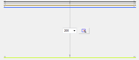
The Scheme templates
command allows to insert to the project predefined lines potentials and
circuit lines, which are used to quickly create schemes.
Predefined lines are adapted to suit both ISO and ANSI standards.
Lines potentials are parametrical, thanks to which it is
possible to specify spacing between the scheme lines.
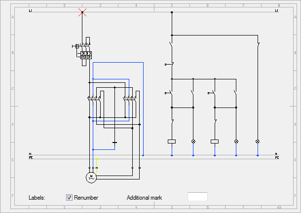
The Scheme templates command
contains predefined electrical schemes that can be used to create typical
schemes. Direct-on-line start of 3-phase motors, reversing systems, star-delta
starting and many more schemes are available.
Each scheme has got components that are initially
pre-numbered. User can enable renumbering and
specify additional marks.
A special group of schemes are distribution center -
circuits. Sets that contain several circuits are available, as well as single
lighting or socket circuits. Thanks to this user can instantly create various
distribution center schemes. Socket and lighting circuits can be used for other
types of circuits - after inserting such a circuit, all that user has to do is
to change the description and the receiver symbol.
When inserting distribution centers, tables that are used to
specify the name, number and circuit parameters are also inserted. To edit this
data, user can use the Edit symbols command or
other commands that are used to edit block attributes.

Example of a typical scheme with insertion of
an additional circuit
Schemes: sheet
templates