CADprofi program possesses several commands used for
inserting symbols into the drawing. It is possible to insert symbols in any
point, into lines, as well as the simultaneous insertion of multiple symbols in
the drawing.
CADprofi symbols have certain properties, thank to
which they behave in a "smart" way, for example automatically adjust the
insertion angle to the line, automatically break the line at insertion point,
adjust the layer depending on the kind of installation etc.
All symbols available in CADprofi program are being
inserted as blocks, which can be copied, deleted or edited with the use of
standard CAD program commands. Most symbols can be also edited with the use of
CADprofi editing commands such as: Quick
edit, Edit symbols and Delete symbols.
Symbols are often used to graphically represent real devices,
armature and other installations elements, therefore it is possible to add
technical parameters, about the products used in the project, to the symbols
(Attributes and descriptions command), as well as
numbering and symbols' marks. This information can be used when describing
drawings when creating graphical legends or
specifications.
Symbols and Marks commands are used to insert symbols into the
drawing.
|
Each command that is used for working with symbols has
got a variety of options used insertion of single or multiple symbols into
the drawing.
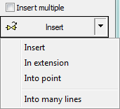
Main options (available after pressing the  button): button):
•
Insert symbol or symbols.
•
Into many lines.
•
In extension.
•
Into point. |
|
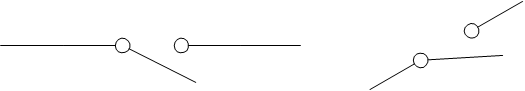
‘Insert symbol’ option
This is the default option that allows to insert symbols in
any point or into a line indicated by user.
|
|
|
Insert into a line |
Insert in any
point |
6
Procedures
Insert symbol
1.
Select the symbols or symbols in any library.
2.
Click the Insert symbol button. The library dialog
window will close allowing insertion of symbols into the drawing.
3.
Point into a line, in which you would like to insert the symbol.
4.
(Optional) Click anywhere in the drawing to insert a symbol.
5.
(Optional) Specify the rotation angle of inserted symbol - this option is
available only if user has selected the Rotate
option in the library dialog window.
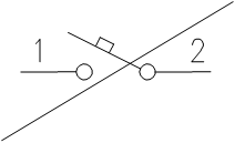
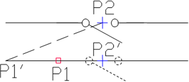
When inserting symbols into lines, the symbol insertion angle
depends on the line angle (the angle specified in the dialog box is being
ignored).
In this case, if user selects the Rotate option, then he will be able to specify symbol's
rotation relatively to the line. This option is very convenient when inserting
symbols which have
a possibility to determine their tap direction, handle
position, flow direction etc.
The angle of such symbol will be dependent on the position of
P2 point.
|
|
|
Without rotation |
With
rotation |
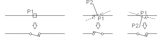
‘Into point’ option
The Into point option may be
used when it is necessary to insert the symbol in a point that lies on a line,
but in such a way that the symbol won't "adjust itself to the line". In this
option, the inserted symbol "ignores" the line, so it does not break it and it
does not take angle from it. This option is used in many situations for example
when inserting sensors, which usually need to touch lines.
Inserting symbol in a point (line was
ignored)
6
Procedures
Insert into indicated
point
1.
Select the symbols or symbols in any library.
2.
With the use of button, pull-down the
insertion list.
3.
Click the Into point button. The library dialog
window will close allowing insertion of symbols into the drawing.
4.
Point into a point in a line, in which you would like to insert the symbol.
5.
(Optional) Click anywhere in the drawing to insert a symbol.
6.
(Optional) Specify the rotation angle of inserted symbol - this option is
available only if user has selected the Rotate
option in the library dialog window.
‘In extension’ option
The In extension option allows
to precisely specify the symbol insertion point in relation to other objects
located in the drawing. This allows to insert a symbol in a point in accordance
with for example another symbol.
|
Inserting in
extension |
6
Procedures
Insert in extension
1.
Select the symbols or symbols in any library.
2.
With the use of button, pull-down the
insertion list.
3.
Click the In extension button. The library dialog
window will close allowing insertion of symbols into the drawing.
4.
Click a line, in which you would like to insert the symbol (P1).
5.
Program will determine a point at the line beginning (P1’). Specify the offset against this point or specify
the symbol insertion point against you would like to specify the location of the
inserted element (P2).
6.
Specify an additional offset or click Enter to
confirm the insertion point.
7.
(Optional) Specify the rotation angle of inserted symbol - this option is
available only if user has selected the Rotate
option in the library dialog window.
8.
Symbol will be inserted in the drawing and the command will end (if user has not
selected the Insert multiple option).
‘Into many lines’ option
Into many lines option gives the
possibility to quickly insert selected symbol into many lines. It allows to
insert selected symbol into all lines that cross with the „indication line”,
that was specified during insertion (P1-P2).
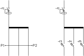
Inserting symbols into many lines
6
Procedures
Insert into many lines
1.
Select the symbols or symbols in any library.
2.
With the use of button, pull-down the
insertion list.
3.
Click the Into many lines button. The library
dialog window will close allowing insertion of symbols into the drawing.
4.
Specify the first point of the “crossing line” that will cross with lines (P1).
5.
Specify the second point of the “crossing line” that will cross with lines
(P2).
6.
The selected symbol will be inserted in all lines that crossed with the
“crossing line”.
 Schemes: working
with
symbols
Schemes: working
with
symbols
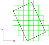
Arrange option
Arrange
option allows user to quickly insert multiple copies of a given object in
a selected layout. This option significantly speeds up the insertion of objects
such as fire detectors, sprinklers, lighting fixtures, and so on.
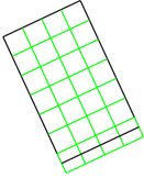
In the first step, the command
evenly divides the selected area into rectangular zones , into which the
object is then placed. The size and arrangement of the zones depend on the
parameters specified in the dialog box.
|
|
|
|
Example
of zoning according to the current LUW system |
Example
of separating zones according to the longest
edge |
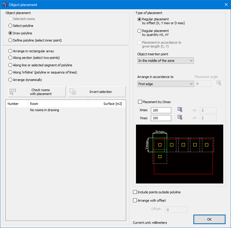
Arrange Objects dialog box
Selected rooms - places the object in the selected
current drawing.
Select polyline - places an object in any closed
polyline indicated in the drawing.
Draw polyline - places an object in a specified area
defined by selecting points (vertices of a polygon).
Define polyline - positiones an object within an
automatically detected boundary after selecting an internal point.
Arrange in a rectangular array
:
• Along the
section -
• Along a line
or selected segment of polyline -
• Along the
infoline -
Check rooms with placement - this option allows user
to select all rooms on the list in which an arrangement has been made with the
currently selected symbol or a related symbol (e.g. a sensor of a different
type).
Invert selection - inverts the selection of rooms
available in the list.
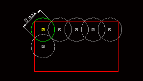
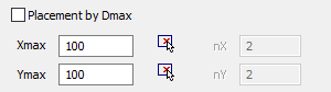
Regular placement by offset (X, Y, max or D max) - a
mode in which the number of columns and rows of the distribution will be
selected so that it does not exceed the specified values of XY spacing or R
radius. This option is recommended when the placed element has an operating
range (e.g. a sensor).
|
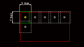
|
|
|
Xmax
Ymax Deployment |
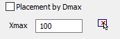
Dmax
Deployment |
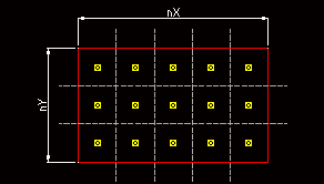
Regular placement by quantity
nX, nY - mode in which user specifies the number of columns and rows, the
distances between elements will be calculated based on these parameters.
|
|
|
|
nX nY
placement |
|
Arrange in accordance to
- orientation of the X and Y directions for the distribution.
Placement angle - the
rotation angle of the distribution.
Object insertion point -
the point of the zone where the block will be placed.
|
Placement by Dmax -
toggles the ability to define Xmax, Ymax or Dmax. |
|
Include
points outside polyline - enabling this option will result in inserting
blocks whose zones overlap the filled area, but their centers lie outside
it.
Notice
If we want to rearrange an
object in a given room or polyline, program will give us the option to
replace it by displaying an appropriate dialog
box. |
Arranging
objects
Usage of symbols inserted with a fixed angle
In order to maintain the project correctness, some symbols
are being inserted with a fixed angle. Examples include gravels and separators.
These symbols should be inserted with a 0° angle. In CADprofi many
symbols have got an enforced insertion angle. When user will insert such symbols
in horizontal or vertical lines, these lines will automatically break. In other
cases, lines are not being broken.
|

|
|
Vertical line |
Horizontal line |
Incline
line |
Notice
For symbols with a fixed
insertion angle, "Angle" and "Rotation" options located in the dialog box
are being ignored. |
Symbols that contain text (visible attributes)
For symbols that contain text (visible attributes)
CADprofi program will automatically adjust angle of the text. Thanks to
this the situation in which text would be displayed "upside down" or "backwards"
is being avoided. User has the following possibilities to adjust texts:
• 0° fixed angle.
• 0° or 90° angle. If symbol is inserted with a 90° angle,
then the text is also rotated by 90°. In other cases the text angle is 0°.
• Automatic angle from -30° to +120°. In these ranges the
text rotation angle is sufficiently readable.
|

|
|
Adjustment of attributes
angle |
Notice
Options for text adjusting are
permanently set for each symbol. User can change these options only for symbols
that were added by the user.
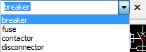
Find symbols
In each dialog window that is used for symbols insertion
there is a search option, thanks to which it is possible to quickly find desired
symbols.
|
The Find field is used to
enter a phrase (full or just a part name of searched symbol). This field
remembers typed words, which allow user to search again from the expanded
list by pressing the  button and
clicking Find. button and
clicking Find. |
|
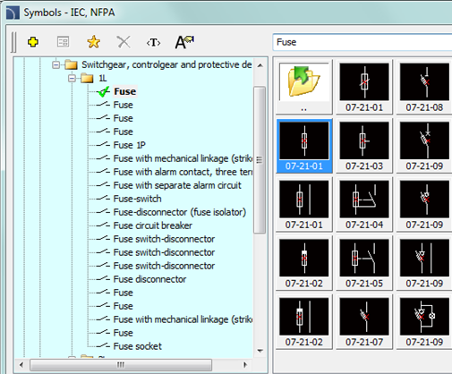
After filling the search field, application will
automatically filter the current library content and display only those
categories which contain the objects that match the search results. Clicking the
Restore button  will display all library objects and end
the search.
will display all library objects and end
the search.
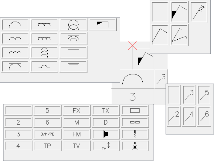
Multivariant symbols
Multivariant symbols are objects, thanks to which in a quick
and easy way user can customize their view or information contained in the
inserted object. In this way, one multivariant symbol can replace many
"traditional" ones, while giving a better possibility to configure their look
and type.
Multivariant symbols may be freely modified, using the Edit symbols command.
Example of a multivariant symbol
Socket - user can specify
the following options:
• socket
type,
• connector
type,
• socket
multiples,
• additional
markings (number of fields, type etc.).
Management of symbols content
CADprofi program possesses several thousands of
symbols grouped in appropriate categories. Witch such a large number it is
sometimes hard to find symbols needed at the moment. On the other hand, when
working on a particular project it is usually not needed to work with more than
several dozens of symbols. In order to speed the work, user can add selected
items to the *Favourites* category thanks to which
he will be able to get a much faster access to them.
It is possible to create sub-categories related to a specific
theme, such as a separate category for symbols used in designing
telecommunication, lighting installation and more. Furthermore one element can
be added to many sub-categories.
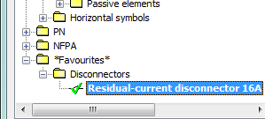
For elements placed in the *Favourites* category it is possible to change their
name, which will be later used in BOMs, legends and descriptions. Change of name
can be also used to user own translations for some symbols from international
standards.
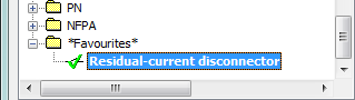
Adding symbols to favourites
Add to favourites  button allows to copy any symbol to the
*Favourites* category. This folder is created
automatically after user has copied the first symbol.
button allows to copy any symbol to the
*Favourites* category. This folder is created
automatically after user has copied the first symbol.
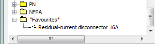
Changing the symbol name
|
Initially, each copied symbol receives the default name
from the original item.
In order to change the symbol name that is located in
the *Favourites* folder, user should first
select it and then press the F2 button to
activate the edition mode |
|
Notice
Changed name will be visible
in tables and descriptions that are created with the Bill of materials
command. |
|
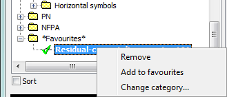
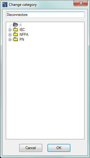
Changing category
In order to change or define a new category, click the
right mouse button on
a desired symbol and from the context menu choose the
Change category option. |
|
|
In the dialog box, user can select an existing category
or enter a new category name. After accepting, selected symbol will be
moved to the defined category.
CADprofi application allows to create many
copies of each symbol and it is possible to place them in different
categories. Thanks to this user can create categories that group symbols
of a specified type or the most common used symbols for a given industry
type. |
|
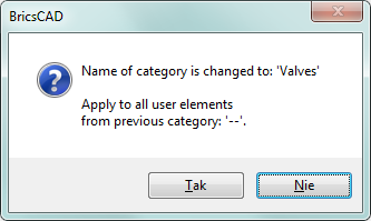
Changing the category or many
symbols
If user is editing a symbol in his native category in
which there are many symbols, then CADprofi application will change
category for all these symbols. |
|
Deleting symbols
It is possible to delete
symbols from the *Favourites* category. To do so,
select the symbol and choose the Delete  option from the dialog window.