Special kind of symbols are plumping objects that are used in plumbing strand diagrams.
In strand diagram drawings it is necessary to maintain the vertical scale on the printouts. Therefore, the sanitary symbols are being inserted in standard size. This size depends on the used design unit (mm, cm, m) that's why the scale change option is blocked.
Plumbing objects can be inserted next to the risers from the right or left side. For some symbols it is necessary to turn on the Mirror X option. Symbols of plumbing objects should be inserted with "0" angle.
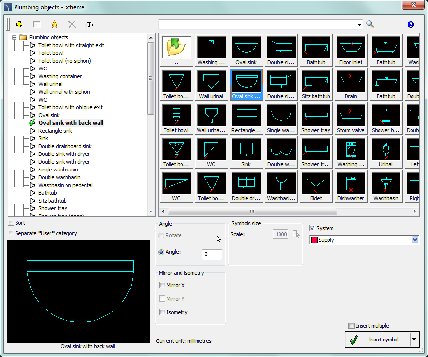
Plumbing objects - scheme dialog window
The basic functionality and symbols options are being described in the Symbols chapter.
A water and sewage system layout is a technical drawing showing the system in a developed (schematic) form, showing the distribution of pipes, risers, connections, and fixtures as if they were laid out on a plane. The actual heights (e.g., floor level, ceiling level, appliance connections) are retained, and the elements are arranged “side by side” in a logical order, rather than in the exact layout of the building.
The first step is to draw a schematic cross-section of the ceilings. The cross-section can be drawn using the Walls command (see p. 142) or with regular lines. In the next step, run the Pipes Schematic command (see p. 196) and draw the water and sewage risers. Then you can insert the sanitary fixtures.
6 Procedures
1.
Run the Plumbing objects - scheme  command.
2. In the Plumbing objects - scheme dialog window select the needed symbol from the appropriate category.
3. Click the thumbnail of the symbol that you would like to insert into the drawing. In the down-left corner you may see the preview of selected symbol.
4. Select the appropriate system.
5. (Optional) Enable the Mirror X option.
6. Click the Insert symbol button, to specify the object insertion point (P1).
7. Symbol will be inserted into the drawing.
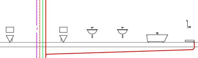
Cross-section of ceilings, water and sewage risers, and symbols for sanitary fixtures
|
Notice For all plumbing objects the insertion point is defined at the floor level. For this reason, before placing the first symbol user should draw a ceiling cross-section. During inserting plumbing objects symbols on strand diagrams user should always indicate the point that lies upper floor edge (P1). |
The next step is to connect the fixtures to the riser. To do this, it is best to use the Lines command with options that automate the connection of objects.
6 Procedures
1.
Run the Pipes  command.
2. In the dialog box, add hot and cold water pipes to the list of drawn lines.
3. Select the Attach to object connection points and Auto-terminate options, and disable the Extended Ortho mode option.
4. Click the Insert button and select the last symbol on the right side of the drawing, i.e., the shower tray symbol. The program will automatically attach itself to this symbol.
5. (Optional) Check that Ortho mode is enabled (F8 key).
6. Select the next point of the drawn pipes, i.e. the point above the shower tray symbol.
7. Select a point on the hot water riser (a horizontal section will be drawn).
8. Program will “detect” the riser, automatically connect the pipes, and finish drawing.

Last object connected
6 Procedures
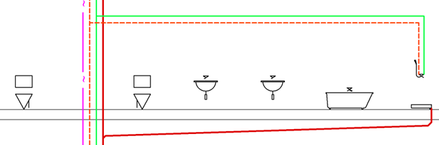
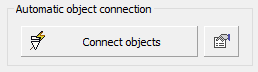
Automatic connection of other appliances on the right side of the riser
1.
Run the Lines command.
2.
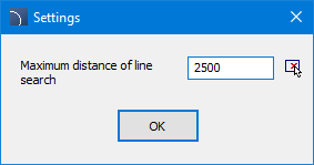
In the dialog box, click the Options button  located behind the Connect Objects button and specify the search range for
distribution lines, e.g., 2500 mm.
located behind the Connect Objects button and specify the search range for
distribution lines, e.g., 2500 mm.
3. Click the Connect Objects button and then select the fixtures on the right side of the riser in the drawing. Finish selecting objects by pressing Enter.
4. Next, select the distribution pipes and press Enter (or press Enter immediately to select all pipes).
5. Program will automatically connect all devices.
6. Connect the devices on the left side of the riser in the same way.
7. (Optional) Insert the necessary fittings and descriptions.
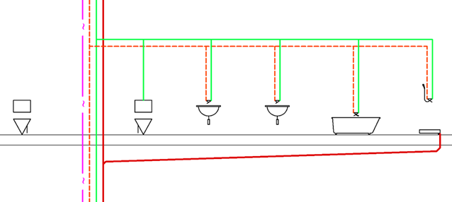
Expansion with connected objects