This wizard allows user to select ZPUE products and place them in specific positions in the scheme. This allows user to quickly and easily define the logical structure of your entire switchboard, focusing solely on product selection rather than manual drawing.
Dialog box - “Energy Distribution Scheme Wizard”
The work is carried out on a matrix containing the following options:
 Insert/Delete column
- inserts an empty circuit before
the indicated matrix column and the ability to delete the entire
column.
Insert/Delete column
- inserts an empty circuit before
the indicated matrix column and the ability to delete the entire
column.
 Load data
- saves all data from the current
schema to the '*.cpelproj' file.
Load data
- saves all data from the current
schema to the '*.cpelproj' file.
 Save data
- loads the schema from the
'*.cpelproj' file.
Save data
- loads the schema from the
'*.cpelproj' file.
 Copy Symbol
- activates copy mode. After
selecting the command, click the cell from which the symbol will be copied to
subsequent cells. To finish, right-click and select Finish Copying
.
Copy Symbol
- activates copy mode. After
selecting the command, click the cell from which the symbol will be copied to
subsequent cells. To finish, right-click and select Finish Copying
.
 Clear All
- Removes all information from the
current scheme.
Clear All
- Removes all information from the
current scheme.
Network layout - possibility to select the type of electrical network (TN-C, TN-S).
Line 'N' drawn from the top - Change the way of drawing the potential line 'N' .
Divide schemes into worksheets - enabling this option will split the inserted diagram into sheets of the selected size.
Insert with drawing frame - enables/disables drawing of the drawing frame.
Sheet size - specifies the size of the sheet on which the diagram will be drawn.
Scheme area - ability to change the area occupied by the scheme on the sheet.
Product numbering - ability to choose the method of numbering products in the scheme.
Number circuits from - starting value for circuit numbering.
|
Product selection - after clicking on the selected cell, a list appears in which user must select the symbol and then select the desired ABB device from the product list.
|
|
Selecting Sliding Cassette - After
selecting and arranging the products, we can choose the appropriate size of the
casette unit for the receiving circuits. Clicking a cell  and selecting it
  will display an additional dialog box with a
list of dedicated casettes units, selected based on the devices installed in the
circuit. Additionally, the casette unit's front panel features active buttons
for selecting additional casette components, such as lights, pushbuttons, and
measuring devices.
will display an additional dialog box with a
list of dedicated casettes units, selected based on the devices installed in the
circuit. Additionally, the casette unit's front panel features active buttons
for selecting additional casette components, such as lights, pushbuttons, and
measuring devices.

|
Circuit information - after clicking the lower button of the matrix, it is possible to enter the name of the circuit (receipt) and additional parameters, such as: power, current and the type and cross-section of the power cable. |
|

In the general settings window, user can fill in basic project data in the title block, such as the investor, project title, status, contractors, etc. User can also manage the visibility of descriptive attributes for additional accessories. The "Show attributes for accessories" option is available.

Bill of Materials command also allows user to automatically generate apparatus views based on the symbols used in scheme. A special ZPUE list - Insert 2D views from selected symbols, is available for this purpose. After selecting this type of list, click the Next > button and select the area containing the desired symbols. After confirming your selection (press Enter), a list of selected products will be displayed. The order of the products in the list corresponds to the order of the symbols in the scheme, so it is usually not recommended to reorder this list.
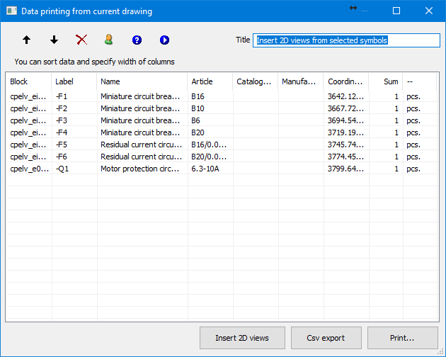
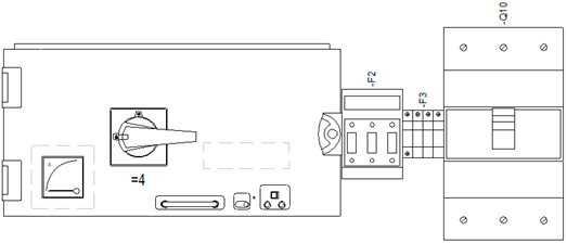
After selecting the Insert 2D Views option, application allows user to select a point and will start automatically inserting elements one by one according to the order in the list.
This option is used to select appropriate types of ZR-W switchgear bays based on devices and withdrawable apparatus (views or symbols) selected from the drawing .
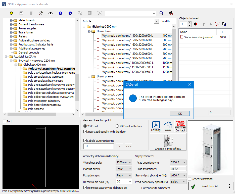
ZR-W switchgear selection dialog box
6 Procedures
1. Run the Product Library command > Low voltage devices and switchboards .
2. Go to the ZR-W switchboards category.
3. Set the switchgear selection parameters and the busbar and distribution currents.
4.
Select the Select field option  .
.
5. Select an area or individual items to include in the cabinet selection. Press Enter to confirm.
6. In the program's dialog box, a list is created with the appropriate number and type of selected switchboard sections.
7.
Before inserting them into the drawing, you can change their order and enable
the  option.
8. Click OK to close the window and then insert the switchboard field view into the drawing.
When inserting symbols and objects from the ZPUE
library, program adds descriptions, technical parameters, etc. This data is
stored as attributes. The Attributes and Descriptions  command allows user to
edit all attributes, including busbar values. All data entered into attributes
will be used when creating reports. A full description of the window's functionality
command allows user to
edit all attributes, including busbar values. All data entered into attributes
will be used when creating reports. A full description of the window's functionality
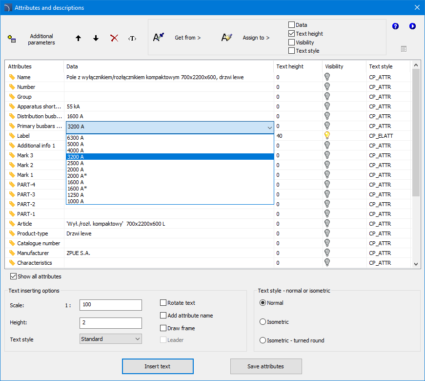
Attributes and Descriptions Dialog Box
 Get from > - allows
user to get selected attributes from the object indicated in the
drawing.
Get from > - allows
user to get selected attributes from the object indicated in the
drawing.
 Assign to> - allows user to assign selected
attributes to objects indicated in the drawing.
Assign to> - allows user to assign selected
attributes to objects indicated in the drawing.
The list of inserted
objects can be ordered using the available options : Up  or Down
  , Delete
  ,
,