In CADprofi program it is possible to create plans and installations cross-sections that include trays, ducts and protective tubes. When drawing an installation line elements and fittings are available (elbows, reducers, tees etc.). Each fitting is a parametrical object, which is being drawn with appropriate program's procedures. Thanks to this it is possible to draw any fittings with specified dimensions. For each element, databases are available, that contain definitions of elements of selected manufacturers.

Tray Protective tube
Trays and fittings are available in the following commands:
•Cable trays – general views – this command contains typical trays and fittings used when designing cable trays.
•Cable trays sequence – general views – this command allows to draw many segments with automatic insertion of elbows.
Trays and ducts
The Cable trays – general views command allows to insert single trays or ducts to the drawing.
After running the command user has to select the needed fitting or tray, specify its dimensions and insertion options. Program possesses functions that automate the connection of elements to each other. It is possible to automatically adapt the tray size and connect it to other elements. Below there are examples with usage of this function.
Examples of inserting fittings
|
Automatic insertion at the end of the tray. 1. Indicate a tray to which you would like to insert an elbow (P1). 2. Specify the elbow direction (P2). |
|
|
|
Inserting a tray with the „join object” option. 1. Indicate and object to which you would like to connect a tray (P1). 2. Specify the length of a new tray (P2). |
| |
When connecting trays or ducts to other installation elements the Diameter fit option is handful, cause thanks to it the inserted element always has the same size, so it will suit the indicated object.
Z+/Z– trays and fittings
Z+/Z- trays represent the vertical tray segments (along the Z axis). On plans for such elements the cross section symbol is also visible. Because of that Z+/Z- tray length has to be specified in the dialog window before adding them to the drawing.
For Z+/Z- trays and fittings it is possible to additionally specify the symbol cross section (Z+,Z- or without symbol) and the insertion point (beginning, axis, end).
 |
 |
Z+ Z– Without any symbol
Retrieving fittings dimensions
During drawing it is often needed to insert similar elements to elements that are already inserted in the drawing. In such case it is convenient to retrieve dimensions from another fitting. After pressing the Copy dimensions button user has to indicate the needed fitting. It is important to avoid indicating fittings that have completely different parameters than the element currently chosen in the dialog window. In such cases, user may experience ambiguity in the data interpretation.
For example: if an elbow was selected in the dialog window, and user selects a reducer then CADprofi won't be able to specify the elbow angle and the radius, because reducer doesn't posses such parameters.

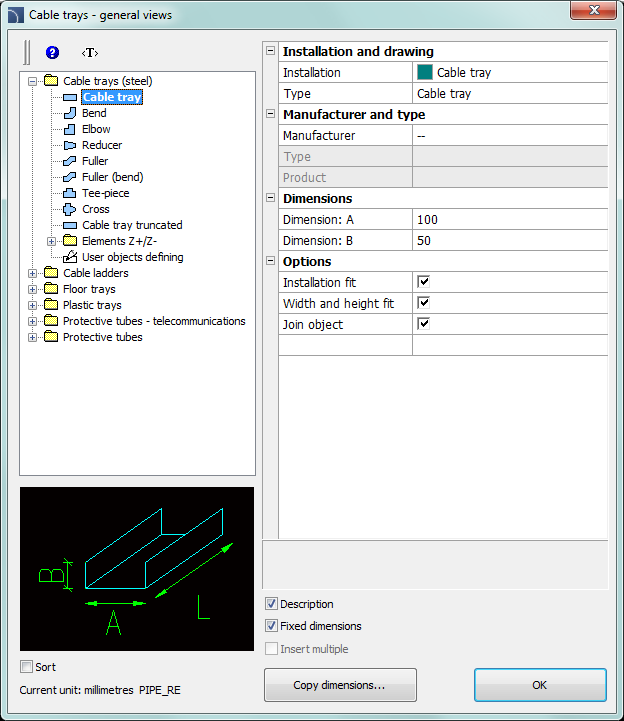
Cable trays – general views dialog window
The Cable trays – general views dialog window contains the following items:
Categories tree – a set of all categories and symbols in the library, shown as a pull-down tree.
Preview – displays the preview of the currently selected element. Right-clicking on the preview window will zoom the view.
Sort – enables/disables categories alphabetical order.
Fixed dimensions – enables/disables the preserve of a basic dimension after inserting objects such reducers. After inserting such element in which the line dimension is being reduced in the next time user runs the command the application will automatically change the default diameter into a reduced diameter (D2). This process is very convenient when designing an installation sequence. However, if user wants to insert a fitting that has an unchanged main cross-section then enabling the Fixed dimensions option will prevent an automatic change of cross-section.
Installation and drawing:
•Installation – gives the possibility to choose the installation kind or define a new one. Initially on the drop-down list only the most important CADprofi systems will be included. However, user has the possibility to develop the list with his own elements (by using the Add to most recently used option), which is located in the Lines, cable trays - scheme) dialog window. Selecting the Others/Edit option will open a new dialog window with full list of available systems.
|
|
|
Type – possibility to
specify the fitting type (normal element, segment etc.).
 |
Elbow types available in the program
Manufacturer and type –
selection of items from manufacturers’ standards or
databases.
CADprofi program allows to draw fittings and 2D trays,
whose dimensions can be specified in two ways:
1.
Drawing based on dimensions specified by user.
To enable this mode, in the
Manufacturer field select „–
–”.
2. Drawing based on manufacturers’ standards or databases. In order to activate this mode select the required manufacturer (or standard).
|
After selecting the manufacturer it is not possible to enter you own dimensions (this option is blocked). |
|
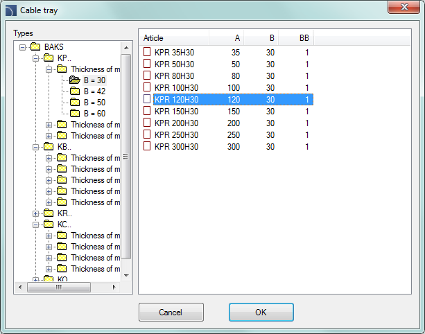
After selecting a specific manufacturer or standard a dialog window will appear with available fittings or lines.

Element selection dialog window
Dimensions – In
CADprofi program it is possible to draw fittings with any dimensions. To
do this, in the Manufacturer field select „– –"
When drawing is based on user selected dimensions
then two field in which user can enter values are available.  button allows to select typical values.
Trays length is determined in the drawing by indicating two points.
Options – additional options that automates the drawing process:
•Join object – automatic connection of inserted element to existing objects. When connecting, CADprofi program will automatically determine the rotation angle and the element insertion point.
•Installation fit – automatic determination of installation kind based on object, to which the inserted element is being connected. Installation kind set in the dialog window is being ignored.
•Diameter fit – automatic identification of installation diameter based on object to which an element is being connected. In the connection point it is possible to insert a reducer or to ignore the line diameter from the dialog window.
•Insert in a sequence – gives the possibility to insert fittings into an existing line or into their extension. If this option is disabled then fittings are inserted on the end.
Procedures
1.
Run the Cable trays - general views  command.
2. In the Cable trays - general viewst dialog window from the list of available categories select Tray, Duct or Protective tube.
3. From the list of installations select the needed kind of installation in order to specify the color and layer for a new tray.
4. (Optional) Specify the values for the Manufacturer and type items.
5. In the Dimensions field specify the Diameter value for the tray.
6. (Optional) Click the Copy dimensions button and indicate an element on the drawing from which you would like to copy the diameter value.
7. (Optional) Enable/disable the Installation fit, Diameter fit, and Join object.
8. Click the OK button to start drawing a tray.
Defining user own fittings
|
When designing installations it is sometimes needed to
use non-standard fittings. In this case, user can define his own fittings,
which will be taken into account during numbering or during creating
BOM. After clicking the OK button, user should select objects from the list that the new fitting is being made up from and to choose the base point. If a fitting is often used then it is possible to add it to the program library by using the User block wizard (check page 106). |
|