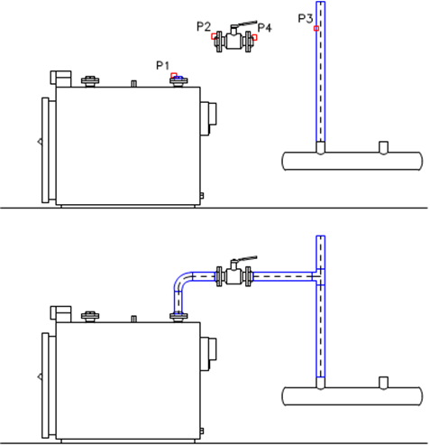
The fastest and the most convenient way to create 2D installations, such as air condition, piping or cable trays is to draw them The fastest and the most convenient way to create 2D installations, such as air condition, piping or cable trays is to draw the lines or sequences of installation lines, which are later automatically connected with the help of the universal Join pipes/ducts command. During the connection creation, CADprofi program lengthen or shorten connected lines and automatically inserts optimal fittings.
Connections can be made on elements that have certain types and connector size. It means that pipes, ducts, trays, armature, pumps and many other devices can be connected.
After running the Pipes\Ducts- general views command, user should indicate lines that he would like to connect. Depending on the position and size of the indicated lines, CADprofi program will propose the right fitting.
The fitting selection and the determination of its size is made in the dialog window. The dialog window layout is always the same as in commands that are used to draw lines, ducts and fittings.
Example:
• In the first stage the lines are drawn.

• In the second stage the lines are connected with automatic insertion of appropriate fittings.

Rules that are used for connecting
•piping installations,
•air condition lines,
•cable trays.
|
•One
line: |
|
|
•Two, three or four
coaxial lines |
|
|
•Lines inserted at
the same angle: |
reduction
fuller |
|
•Elements inserted
at different angles:
|
|
|
•Three lines from
which two are coaxial: |
|
•When connecting flex lines with other lines inserted at different angles, the same rules are used as for circular lines.
•Some connections can't be made due to lack of appropriate fittings, e.g. there are not tee flex fittings.
|
•Connection of
equipment elements of air condition ducts with other
ducts: |
|
•It is also possible to make connections between other objects e.g. between armature, objects, lines and fittings. In each case, the rules for creating connection are the same as when connecting pipes or ducts.
•Program also allows to connect lines that are insulated.
Notice
Application doesn't allow to automatically connect lines and ducts that belong to different kinds of installation. If it necessary to connect for example a piping installation with an air condition installation, user will have to insert appropriate fittings manually.
6 Procedures
1.
Run the Join general elements  command.
2. Indicate elements that you would like to connect. Confirm by clicking the right mouse button or by pressing the Enter key.
3. In the newly opened dialog window select the fitting type that you would like to use.
4. (Optional) Specify the necessary dimensions of selected fitting.
5. (Optional) Specify the Thickness of insulation value for the selected fitting.
6. Press the OK button to close the window and make the connection.

Examples of connections between fittings, lines and objects: