The Parametrical armature command allows to insert to the drawing armature views, "in-line" pumps and other piping objects. For each element, databases are available that contain standardized elements and elements based on manufacturers types. All elements are parametrical objects. It means that when user inserts an object into the drawing, he has the possibility to determine dimensions such as length, width, connection sizes or the dimensions of a manual valve knob as well as other dimensions. This feature gives user a lot of opportunities, because through self-determination of dimensions, user can use any devices, even those that are not available in standard program databases.

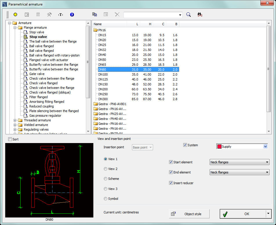
Parametrical armature dialog window
Parametrical armature dialog window contains the following elements:
List of categories - displays a list of available elements grouped in categories and subcategories.
Sort - enables/disables categories alphabetical order.
Detailed list - list of elements available for the selected category.
Preview - displays the preview of the currently selected element. Right-clicking on the preview window will zoom the view.
View and insertion point - view selection and object insertion points. Available options depend on the type of object.
Object style - options that allow to specify the object style and the level of object detail.

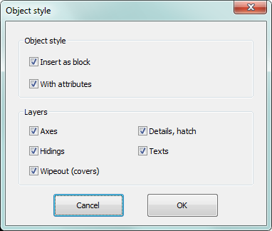
Object style dialog window
•Insert as block -allows user to insert an element that is exploded into component parts or a one single object (block).
•With attributes - enables/disables adding of attributes to the inserted object.
•Axes - enables/disables an option to draw axis in the inserted object.
•Hidings - enables/disables drawing elements that are hidden in an object.
•Wipeout (covers) - enables/disables addition to the inserted elements Covers (Wipeout) type objects.
•Details, hatch - enables/disables drawing of hatches and object details such as holes in the flanges, arrows that indicate the direction flow and others.
•Texts- enables/disables drawing of potential texts in objects.
|
Notice All „Object style” settings will be remembered and used when user runs the command again. |
Parameters - options that specify additional parameters of inserted object.
•System - if in the program options, the extended layer name structure is enabled then objects will be inserted on layers depending on the kind of installation (system). In case of inserting objects into an existing line then the System option is being ignored and the object layers depends on the line kind.
•Start/End element -gives the possibility to connect to the object additional elements. For example this option allows to insert together the valve flange together with properly selected flanges (at the start and end of the valve).
•Insert reducer - automatic insertion of a reducer. This option is used when inserting and object into an existing line if the object nominal diameter is different from the line diameter.
OK - allows user to insert selected object into the drawing.
Insertion options  - expands the list of available insertion
options:
•Insert (specify style for object) - inserts selected object with a possibility to change options in the Object style dialog window.
•Insert (specify all dimensions) - inserts selected object with possibility to specify all dimensions that can be edited. It is also possible to save the user dimensions by Creating and extending the user type of series Creating and extending user type of series.

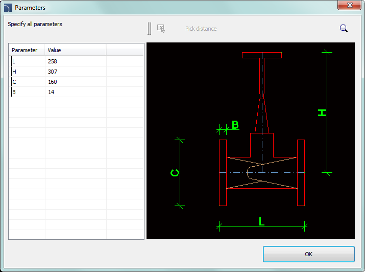
Parameters dialog window
When user selects this option, a dialog window will appear
allowing to enter values for each dimension.  button allows to specify the selected
dimension directly on the drawing (by indicating two points).
6 Procedures
1.
Run the Parametrical armature  command.
2. In the Parametrical armature dialog window select the needed object category. After that the element preview will be displayed and on the detailed list you will be able to see all available element types and sizes.
3. (Optional) If the list of available types possesses subcategories double click on a category will expand it and you will be able to see its content.
4. (Optional) Right click on any item and from the menu choose the Expand all/Collapse all option.
5. Choose the needed element form the detailed list.
6. (Optional) Change the View for the selected element.
7. (Optional) Change the settings for the Object style options.
8. (Optional) Switch on the System option and select the installation from the list.
9. (Optional) Set the: Start element, End element and Insert reducer.
10. Click the OK button to insert selected object into the drawing.
11.
(Optional) Expand the  button and
select Insert (specify all dimensions) to specify
dimensions of inserted object.
12.
(Optional) Expand the  button and
select Insert (specify style for object) to prior
before inserting an object make changes in the Object
style option.
13. Click on the edge of a line, in which you want to insert a selected element, and then specify the object insertion point in the indicated line.
14. (Optional) Click at any point in the drawing to insert the element.
15. Specify the element rotation angle or the insertion direction if the element is inserted into a line.
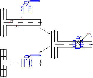
Inserting armature in a 2D line
In order to insert armature into a line user should:
1. Indicate (P1) point. Application will automatically choose the nearest line end, as the reference point (P1’).
2. Afterwards specify the actual insertion point. It is possible to enter in the command line the distance from the reference point (from the beginning of the line) or to indicate a point (P2). If the point will be indicated further than the line length then program will automatically extend the line and insert the armature at its end.
3. For many objects it is also possible to indicate the (P3) point in order to determine the direction of inserted object.

An example of inserting armature into lines:

Threaded valve with a nominal diameter corresponding the line diameter.

Threaded valve with a nominal diameter smaller than the line diameter with the Insert reducer option enabled (automatic reducer insertion).

Threaded valve with a nominal diameter bigger than the line diameter with the Insert reducer option enabled (automatic reducer insertion).