The Edit elements command allows
to edit 2D lines and fittings. This command depends on the type of the selected
object. If user directly indicated any line segment, then it will be possible to
edit it length by indicating a new end point. If user selects the Edit ("E" key) in the command line then a dialog window
will appear allowing user to edit the selected segment parameters. Indicating
any fitting will open the dialog box that allows user to edit all fitting
parameters.
6
Procedures
Line edition
1.
Run the Edit elements  command.
2.
Select the line that you would like to edit.
3.
Specify the ending point for the selected line.
4.
(Optional) Select the Change length („L” key in the
command line) option to specify a new length without changing the line insertion
angle. Optionally it is possible to select the Delta option to specify the length of the line lengthen
(in drawing units) or the Percent option for
lengthening the line in percent.
5.
(Optional) Select the Edit option from the context
menu or from the command line ("E" key) in order to open the dialog window that
gives user the possibility to change line parameters.
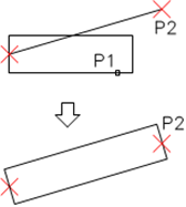
|

Direct change of the line length |

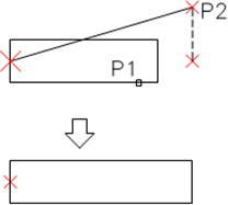
Edition after selecting the Length
option |
6
Procedures
Fitting edition
1.
Run the Edit elements  command.
2.
Select the fitting that you would like to edit.
3.
In the dialog window specify new parameters for the selected fitting.
4.
Click the OK button to update the fitting on the
drawing.
For some fittings it is possible to change their type, for
example when editing elbows, it is possible to change the elbow into a
segmented, two-segmented or to an elbow with an inspection door.

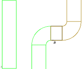
Examples of changing the type of fitting
 When editing fittings
user can use the Copy dimensions > option, thank
to which in an easy and convenient way he can get dimensions from other elements
that are located in the drawing.
Changing the system type for lines and 2D fittings
Elements that belong to the appropriate system or
installation are automatically located on specified layer. The CADprofi - Edit command allows to change the system for
individual fittings. System change can also be performed by moving elements into
another layer. In CAD programs there are many ways to change object layers. A
very convenient way is to use the match properties command:
|
Example:
To change the system (for example in air condition
installation from supply air into exhaust air), user should run the Match properties command, select the source object
and then select all objects for which he would like to change the layer
into exhaust air installation layer.
Notice:
Circular, rectangular and flex lines that
belong to the same system are located on different layers: |

|
- circular lines are located on the 2Dx_PRO_xxx
layer
- rectangular lines are located on the 2Dx_PRE_xxx
layer
- flex lines are located on the 2Dx_PFX_xxx layer
The beginning of layer name (2DL) means air condition, the
next part (PRO, PRE or PFX) means line form, and the ending (xxx) means system
or installation.
 command.


 When editing fittings
user can use the