In CADprofi program schematic walls are being drawn with lines that lie on appropriate layers. Composite walls can contain several layers that represent walls by material (brick, concrete etc.) or wall by purpose (load-bearing wall, insulation etc.).
Drawing single layer walls is possible after selecting the needed wall type and clicking the OK button. Such a process however does not allow to change drawing settings and wall thickness. These options are only available for walls that were added to the list that contain a wall definition. This list also allows for drawing of composite walls.
Due to very large variety of materials used in the construction branch, when starting your work with CADprofi it is recommended to define your own walls with your materials or structural elements.
Walls dialog window
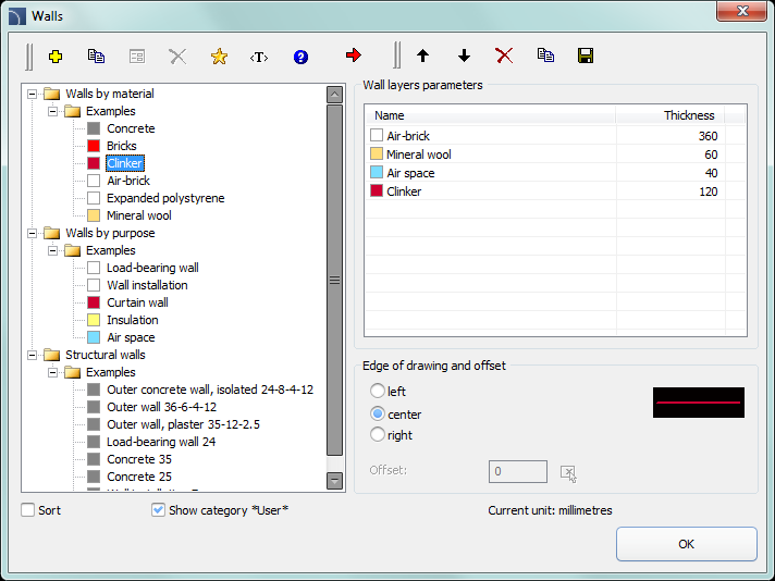
The Walls dialog window contains the following elements:
Wall types menu:
•Define new  –
allows to add a new position to the list as a user wall
–
allows to add a new position to the list as a user wall
•Copy  – copies
the selected wall with all its parameters, therefore creating an element made by
user. Copied lines may be edited.
– copies
the selected wall with all its parameters, therefore creating an element made by
user. Copied lines may be edited.
•Edit  – opens
the edit properties window of a selected user created wall
– opens
the edit properties window of a selected user created wall
•Delete  –
deletes the selected wall from the list.
–
deletes the selected wall from the list.
•Add to favourites  – adds the selected line to the *Favourites*) list.
•Add element to a list  – adds the selected line to the List of wall layer parameters.
Menu of wall layer parameters – allows to manage the content of the selected walls list.
•Move selected rows down  – moves the selected wall one position
down.
– moves the selected wall one position
down.
Move selected rows up  – moves the selected wall one position
up.
– moves the selected wall one position
up.
•Remove selected rows – deletes the selected wall from the
list.
•Copy selected rows – copies the selected wall and adds it to
the list.
•Save as a structural wall  – allows to save the current list of
selected walls as a structural wall.
– allows to save the current list of
selected walls as a structural wall.
Wall layer parameters – provides a summary of wall layers.
Thickness – specifies the thickness of specified layer in a composite wall.
Edge of drawing and offset – options that are used to determine the way of wall drawing and the offset.
•Left/Center/Right – drawing the wall with the axis or with an edge of the indicated points.
•Offset – an offset of the drawn lines from the points that are actually indicated in the drawing.

|
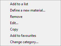
Pop-up menu – options menu for selected element/category which is available by clicking the right mouse button. Commands included in the menu are similar to the commands available on the dialog window toolbars. |
|
Procedures
1.
Run the Walls  command.
2. In the newly opened dialog window pull-down the category that contains the desired wall kind.
3.
Select the desired wall type and click the Add element to
a list button or double click
on it in order to put it on the list.
4. (Optional) Repeat steps 2 and 3 in order to add more lines to the list.
5.
(Optional) Using the Copy selected rows , Remove selected
rows buttons add or remove the
selected layer from the list.
6. Specify the thickness for each wall layer.
7.
(Optional) Using the Move selected rows down/Move selected rows
up buttons change the order of
the lines on the list.
8. Specify the edge of drawing and offset.
9. Click the OK button in order to start drawing the wall.
10. Specify the starting point and next walls segment points (e.g. P1, P2, P3, P4). In order to finish drawing press the Enter or Esc key. It is also possible to close the command with the Close option (C key), thanks to this program will draw the last segment that will connect itself with the first segment of our drawn wall.

|
Hint Drawing with an offset can be used when drawing wall installations. |
Procedures
1.
Run the Walls command.
2.
Select the desired wall installation type and click the Add element to a list .
3. Specify the wall thickness.
4. Specify the edge of drawing as „left” and the offset, as e.g. 360 cm.
5. Click the OK button in order to start drawing the wall.
6. Specify the starting and the end points (P1, P2). The wall will be drawn with a specified distance from the indicated points.
7. Finish the drawing with the Enter or Esc key.

Edit walls materials
CADprofi allows users to define new walls types and to edit them.
Edit walls materials dialog window
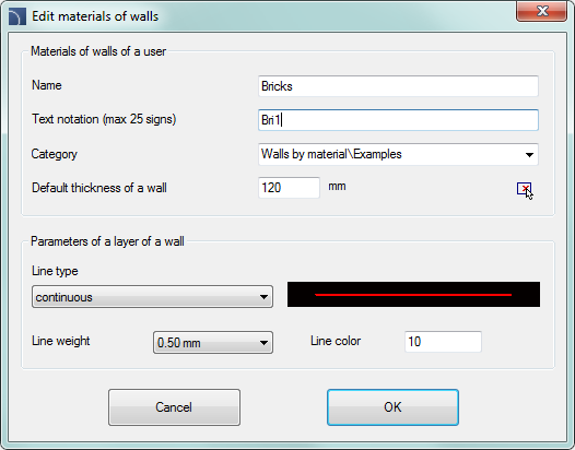
The dialog window contains the following items:
Name – name of edited wall layer.
Text notation – text marking for lines used as an ending of layer’s name in the extended layer structure (e.g. „concrete” wall type can lie on a 2DA_WAL_Bet layer).
|
Notice It is recommended to use „unique values” of text notations in order to ensure proper recognition of lines by CADprofi. |
Category –category in which the selected wall type will be saved.
Default wall thickness – wall thickness that is used as a default value when the selected wall layer is being added to the wall layer parameters list.
Wall layer parameters – CAD settings for the layer, on which the selected wall type will be drawn. User should specify the color and both the line width and type for the appropriate layer.
Procedures
1.
Run the Walls command.
2.
Click the Define new button in order to add a new wall type to
the existing database. New element will be added to the *User* category. A new Edit
window will open, in which user will be able to specify all wall parameters.
3.
(Optional) Select an existing line and click the Copy button to
create a new item. Selected line will be used as a template.
4.
Click the Edit button in order to specify newly created
wall parameters.
1.
Run the Walls command.
2.
(Optional) If the wall type that you want to edit is located on the list of
wall layer parameters, then you will need to remove
it first from the list, to do this, select the element and click the button.
3. In the *User*category select the wall type that you would like to edit.
4.
Click the Edit button. A new edit dialog window will
open.
5. (Optional) Specify the wall type Name.
6. (Optional) Specify the Text notation for the CAD wall layer (not recommended, if the element has been already used in the drawing).
7. (Optional) Specify the Category.
8. (Optional) Specify the default thickness for the selected wall type.
9. (Optional) Specify the wall layer parameters: type, color and line thickness.
10. Click the OK button to accept the changes.
Notice
If user changes the parameters of CAD wall layer, which was previously added to the drawing, then in order to update it, user will have to draw a new wall segment with new settings.
Changing the text notation for walls that have already been inserted in the drawing will make them unknown for CADprofi.
 Drawing walls