The Doors, windows command allows to insert doors and windows in both plan and view. For each objects databases are available that contain woodwork elements. All objects in the library are parametrical objects. It means that user has the possibility to specify all the dimensions when inserting objects to the drawing. This feature gives user a lot of opportunities because he is able to specify dimensions on his own, even for elements that are not in the standard program databases. If user inserts windows and doors in plan then he has to specify the wall thickness, in which he wants to insert the element. Providing the correct wall thickness will allow to automatically hide the wall lines, in which the element will be inserted. Application is able to automatically detect the thickness of wall that was indicated by the user on condition that all the lines (of the multi-layered wall) are parallel and the total thickness does not exceed 600 mm.
For thicker walls or the ones that don't meet the requirements user must specify the B dimension during insertion or by using the Insert option (specify all dimensions).
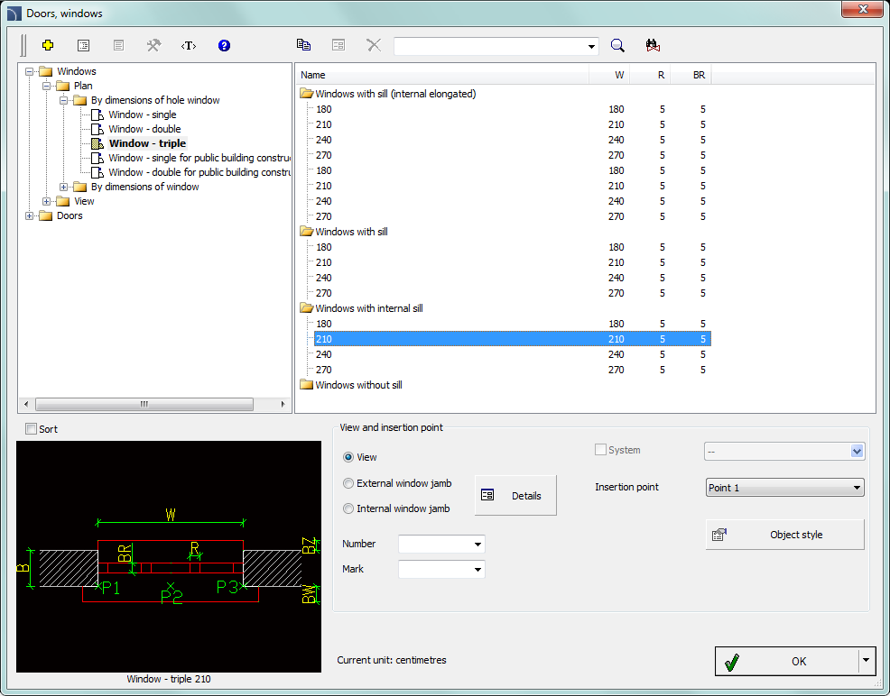
Doors windows dialog window
The dialog window contains the following items:
List of categories – displays a list of available elements grouped in categories and subcategories.
Detailed list – contains a list of available element types with various dimensions.
Preview – displays the preview of the currently selected element. Right-clicking on the preview window will zoom the view.
Sort – enables/disables categories alphabetical order.
View and insertion point – view selection and object insertion points. For all library objects a primary view is available (mostly 2D). Additional views are available only for some objects (e.g. Internal window jamb and External window jamb are available only for plan windows).
Number/Mark – data assigned to inserted element, it is used during insertion of Carpentry symbols (check page. 126).
Insertion point – possibility to choose the objects base point (insertion point). Insertion points are marked on the preview as P1, P2 etc.
Object style – options that allow to specify the object style and the level of object detail.
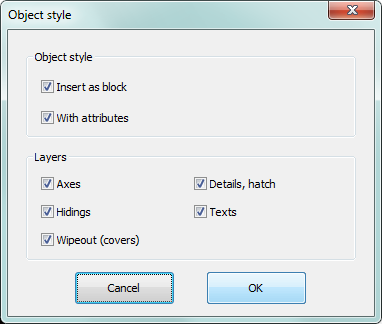
Object style dialog window
•Insert as block –allows user to insert an element that is exploded into component parts or a one single object (block).
•With attributes – enables/disables adding of attributes to the inserted object.
•Axes – enables/disables an option to draw axis in the inserted object.
•Hidings – enables/disables drawing elements that are hidden in an object.
•Wipeout (covers) – enables/disables addition to the inserted elements Covers (Wipeout) type objects.
•Details, hatch – enables/disables drawing of hatches and object details such as holes in the flanges, arrows that indicate the direction flow and others.
•Texts– enables/disables drawing of potential texts in objects.
|
Notice All „Object style” settings will be remembered and used when user runs the command again. |
Details – button that allows to specify dimensions for details that are visible in certain views such as Internal window jamb and External window jamb. Clicking the button will open a dialog window with visible current value dimensions.
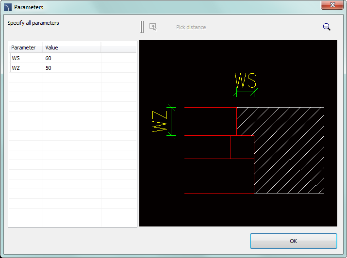
Parameters dialog window
OK – closes the library and allows to insert the object into the drawing.
Insertion options  – expands the list of available insertion
options:
– expands the list of available insertion
options:
•Insert (specify style for object) – inserts selected object with a possibility to change options in the Object style dialog window.
•Insert (specify all dimensions) – inserts selected object
with possibility to specify all dimensions that can be edited. After selecting
this option a Parameters window will appear
allowing user to specify values for each dimension. It is also possible to
determine dimensions directly from the drawing. In order to do so, user has to
activate the value edit field and then click the Pick
distance  button. It is also
possible to save the user dimensions by Creating and extending the user type of
series Creating and extending user type of series).
button. It is also
possible to save the user dimensions by Creating and extending the user type of
series Creating and extending user type of series).
|
Hint By default, in the "Parameters" window displays the dimensions of the object selected in the command main dialog window. |
Procedures
1. Run the Doors, windows  command.
2. In the dialog window choose the needed element (e.g. window projection).
3. (Optional) Select View for selected object, its Insertion point and and specify the Object style options.
4. Click the OK button in order to insert the element in the drawing.
5. (Optional)
With the use of the button expand the
list of insertion options and select Insert (specify all
dimensions), in order to specify the object dimensions.
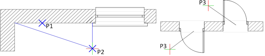
6. Indicate the insertion point. If the selected point will be located on a wall that was created with CADprofi command (P1) then application will automatically determine the required block width and allow to slide the window along the line.
7. Specify the block location point (P2), use the Reference (R), in order to measure the length from any point.
8. (Optional) Indicate the rotation point for the inserted object.
9. (Optional) Specify the wall thickness for the inserted window.
10. (Optional) During the insertion of doors on projections indicate the P3 point that defines the block insertion side.
Hint
Use the Quick
edit, command to change the windows and doors insertion
side.
Use the Insert (specify all dimensions) option in order to define the
wall thickness before inserting the block.
Inserting doors and windows without WIPEOUT
If the doors or windows are being inserted in the wall without hidings (without Wipeout), then after their insertion it may be needed to "cut" the wall lines with the help of the _Trim command.

View after inserting a window View after the wall is „cut”
