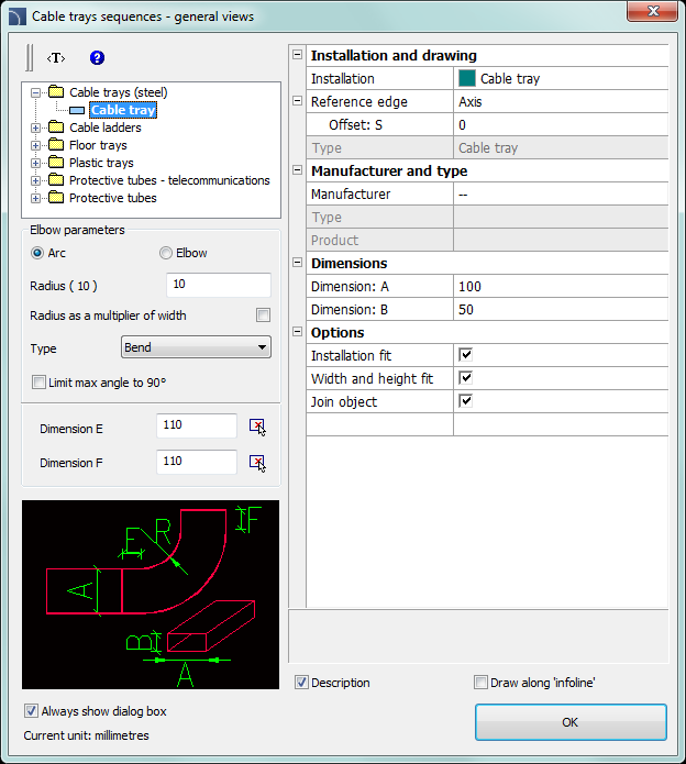
The Cable trays sequence - general views command allows to create trays and protective tubes sequences with automatic insertion of elbows that have parameters defined by user (or without elbows). This command has the ability to disable the display of the dialog box, allowing user to immediately start drawing trays sequences with the last used settings.

2D Cable trays - sequence dialog window
Graphical layout and basic functionality of the dialog window is similar to the Cable trays – general views). Additional options available in this command:
Elbow parameters – a group of options that allow to specify parameters of elbows.
•Radius – allows user to determine the radius or radius ratio for elbows inserted between each tray segments.
•Radius as a multiplier of width – enables/disables the possibility to determine the radius through the width multiplier.
•Type – allows user to choose the elbow type that will be used in the sequence.
•Limit max angle to 90° – enables/disables the possibility to reduce the line sequence elbow angle to 90°.
Dimension E/Dimension F
– allows to specify both E and F dimensions (that are visible on the preview).
 button allows to specify the
dimension by indicating two objects on the drawing.
|
Hint If the „Always show dialog box” option was disabled then if user wants to enable it again he has to choose Settings (abbreviation „S” in the command line) after running the command. |
Reference edge – right
or left edge. Edge is indicated accordingly to the drawing
direction.

Procedures
1.
Run the Cable trays sequence - general views  command.
2. (Optional) If the dialog window didn’t appear then start drawing or select the Settings (S key) option, to change the settings.
3. In the dialog window choose the needed kind of tray.
4. Choose installation kind.
5. (Optional) Specify the values for Manufacturer and type controls.
6. Specify the line Diameter (or cross-section) for the tray or protective tube.
7. (Optional) Enable/disable the Installation fit, Diameter fit, and Join object.
8. Click the OK button to start drawing a tray sequence by indicating the points.
How to draw
When drawing users should indicate points (P1, P2 etc.). If you draw by the axis and without an offset line segments are being inserted along with the indicated points.
|
|
|
|
Protective tube |
Flex tube
|
|
|
|
|
Rectangular pipes with elbows |
Rectangular pipes with arches |
When drawing with an offset the tray sequence is being drawn with a specified distance from the indicated points.
An example of drawing trays accordingly to the edge and with an offset:
