The Modular and
industrial electrical devices command contains many types of connection
apparatus, protection and other components used in electrical projects. For all
apparatus both views used when designing switchgears and when symbols on schemes
are applied. In case of inserting apparatus views it is possible to create a
list of objects to insert, which is also used to
simultaneously insert many objects to the drawing.
If user inserts symbols,
he should use all policies and procedures described in the IEC and NFPA Symbols chapter.
After inserting apparatus view it is possible to use the Create alternative view command in order to obtain in a convenient way symbols for each apparatus. It is also possible to obtain apparatus views on the basis of previously inserted symbols. Using this command user can quickly create a scheme based on the switchgear view or vice versa.
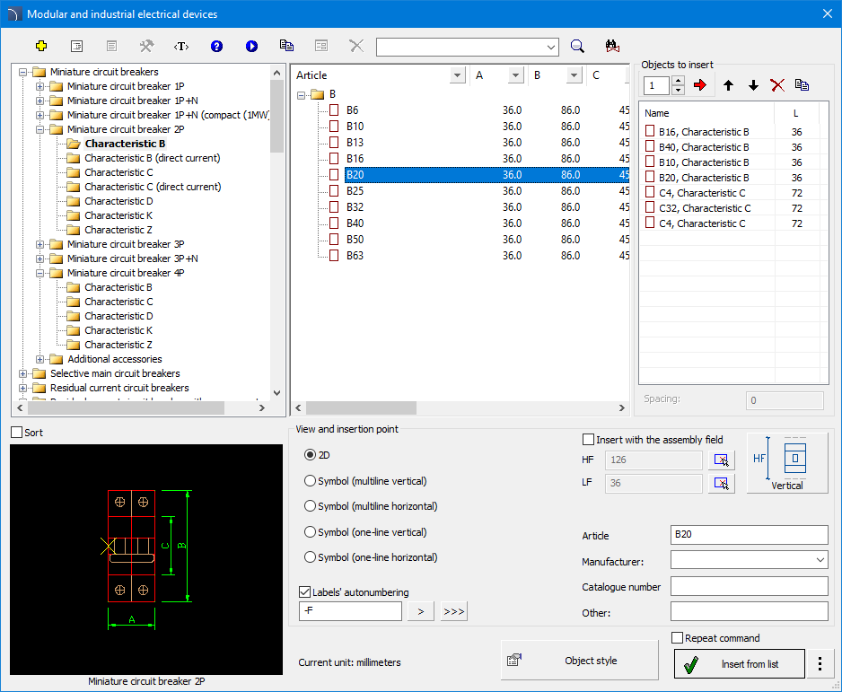
Modular and industrial electrical device dialog window
The method of working with object has been described in
previous chapters.
This command also contains the
following elements:
Objects to insert - list
of objects that will be inserted into the drawing.
The Add element to a list  button adds
object to the list of objects to insert.
button adds
object to the list of objects to insert.
Insertion options - when inserting a single, user can
use other option than the default one to insert an object in the drawing. The
 button expands the list of
available insertion options:
button expands the list of
available insertion options:
•Insert (specify style for object) - inserts selected object with a possibility to change options in the Object style dialog window.
•Insert (specify all dimensions) - inserts selected object with possibility to specify all dimensions that can be edited. It is also possible to save the user dimensions by Creating and extending the user type of series Creating and extending user type of series.

6 Procedures
1.
Run the Modular and industrial electrical
devices command.
2. In the dialog window select the appropriate category.
3. The detailed list that contains a list of lighting fixture there is also a list of available manufacturers and series of types.
4. (Optional) Double click on a series of types in order to expand it display its content. In order to expand all series of types click the right mouse button and from the context menu select the appropriate option.
5. (Optional Change the View for the selected element.
6. (Optional) Change the Object style settings.
7.
Select an element by double clicking or select it and click the Add element to a list button.
8. Continue with filling the list by repeating the steps 2 - 7.
9.
(Optional) Organize the list with the help of the Copy
 , Delete
Move selected rows down
 or Move selected rows down
  buttons.
10. Specify the label and number of the first apparatus. Next apparatus will be inserted with consecutive numbers.
11. Click the OK or Insert from list button, to insert object into the drawing.
12. Specify the insertion point and the objects rotation angle.
 Automatic
obtaining of apparatus view upon symbols
Automatic
obtaining of apparatus view upon symbols