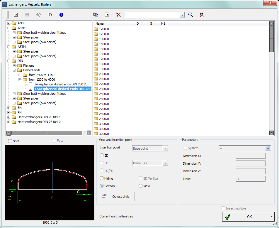
The Exchangers, pipes, fittings command contains many elements that are used in designing heat exchangers, vessels, boilers etc. Elliptical bottoms, flanges, pipes, elbows, reducers and other elements are available. Most elements can be inserted into the drawing in side, top and cross-section views.
A unique program feature is the possibility to calculate the optimal distribution of the heat exchange according to the DIN 28184–1 and DIN 28184–2 standards. It is also possible to save the user dimensions by Creating and extending the user type of series Creating and extending user type of series).

Exchangers, pipes, fittings dialog window
Options covered in this dialog window were described in previous chapters (check page 369).
Procedures
1.
Run the Exchangers, pipes, fittings  command.
2. In the dialog window select the needed object category. After that the element preview will be displayed and on the detailed list you will be able to see all available element types and sizes.
3. (Optional) If the list of available types possesses subcategories double click on a category will expand it and you will be able to see its content.
4. (Optional) Right click on any item and from the menu choose the Expand all/Collapse all option.
5. Choose the needed element form the detailed list.
6. (Optional) Change the View for the selected element.
7. (Optional) Change the settings for the Object style options.
8. (Optional) Select the Enter all dimensions option to specify inserted objects dimensions, for example a pipe.
9. Click the OK button to insert selected object into the drawing.
10. Specify the insertion point on the drawing.
11. Specify the object rotation angle. For certain objects (e.g. for pipe views) specify the second point thanks to which you will determine the length.
|
When insert heat exchangers it is possible to select different flow direction according to the DIN standard. Apart from that it is possible to specify any dimensions for spacing and other arrangement of exchanger. After specifying the diameter of the heat exchanger shell, program will select the optimum distribution of tubes that form the part of the exchange area. It is also possible to make calculations after specifying the total amount of tubes. In this case program will calculate the minimum diameter of the heat exchanger shell and draw the optimal distribution of the exchange area. Thanks to calculation user will receive the information about the total exchange distribution area and the number of tubes in each heat exchanger shell. |
|
|
Example of an apparatus that consists of: bottoms, shells, nipples and flanges
| |
|
|
Calculations result and the heat exchanger corss-section |
The command also allows to quickly draw sequences of pipes with automatic insertion of appropriate elbows. In this case, in the dialog window from the Steel pipe - sequence category select the needed size of pipes and draw along the consecutive points.
|
The selection of elbows is done automatically in such a way to best match the shape of the designed installation based on the points indicated by the user. |
|
Procedures
1. Run the Exchangers, pipes, fittings  command.
2. In the dialog window in the Steel pipe - sequence category select the appropriate pipe size.
3. (Optional) Change the view for the drawn sequence to 2D, Hiding or Section.
4. Click the OK button to start drawing the line sequence by indicating the consecutive points.
1. Run the Exchangers, pipes, fittings  command.
2. In the dialog window select the needed object category. After that the element preview will be displayed and on the detailed list you will be able to see all available element types and sizes.
3. (Optional) If the list of available types possesses subcategories double click on a category will expand it and you will be able to see its content.
4. (Optional) Right click on any item and from the menu choose the Expand all/Collapse all option.
5. Choose the needed element form the detailed list.
6. (Optional) Change the View for the selected element.
7. (Optional) Change the settings for the Object style options.
8. (Optional) Select the Enter all dimensions option to specify inserted objects dimensions, for example a pipe.
9. Click the OK button to insert selected object into the drawing.
10. Specify the insertion point on the drawing.
11. Specify the object rotation angle. For certain objects (e.g. for pipe views) specify the second point thanks to which you will determine the length.