The Standardized parts command allows to insert to the drawing standardized elements such as: screws, nuts, rivets, keys, bearings, wedges etc. All objects has got different views, which allows to create cross-sections, hidings etc.
For all objects there are databases available with many national and international standards, including: PN, EN, ISO, DIN, GOST and ANSI. It is possible to specify which standards should be available to the user. To do this, user should select which standards should be visible in the CADprofi - Options command (in the Standards available in the program card).
All elements are parametrical objects. It means that during inserting them into the drawing user can specify all dimensions. This feature gives user a lot of opportunities, because with the possibility to determine the dimensions, he can use any devices even those that are not in the standard program databases.

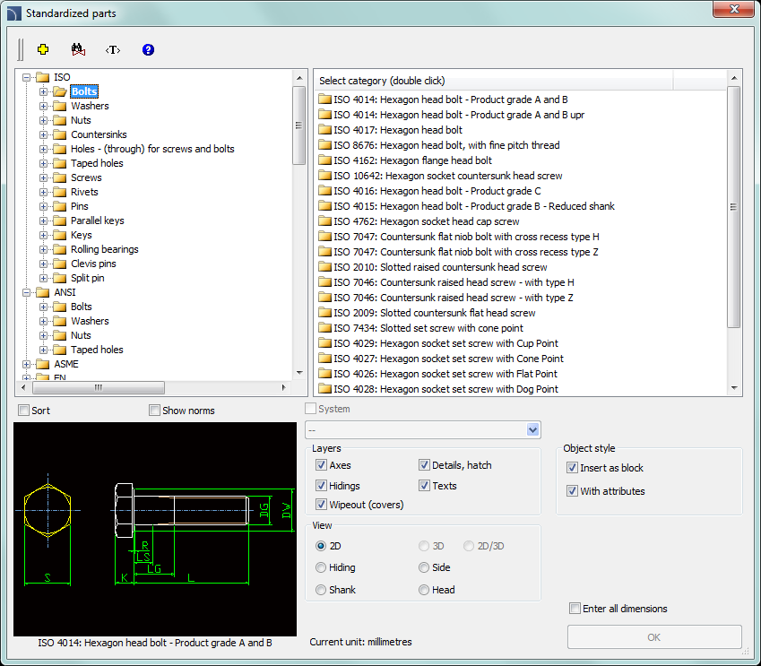
Standardized parts dialog window
The Standardized parts dialog window contains the following items:
Categories tree – a list of all available elements divided into categories (standards) and subcategories.
Detailed list – contains a list of available element types with various dimensions.
Preview – displays the preview of the currently selected element. Right-clicking on the preview window will zoom the view.
Sort – enables/disables categories alphabetical order.
Show norms – enables/disables displaying symbols according to standards.
View– object view selection. Available options depend on the selected element.
Object style – options that allow to specify the object style and the level of object detail.
•Insert as block –allows user to insert an element that is exploded into component parts or a one single object (block).
•With attributes – enables/disables adding of attributes to the inserted object.
•Axes – enables/disables an option to draw axis in the inserted object.
•Hidings – enables/disables drawing elements that are hidden in an object.
•Wipeout (covers) – enables/disables addition to the inserted elements Covers (Wipeout) type objects.
•Details, hatch – enables/disables drawing of hatches and object details such as holes in the flanges, arrows that indicate the direction flow and others.
•Texts– enables/disables drawing of potential texts in objects.
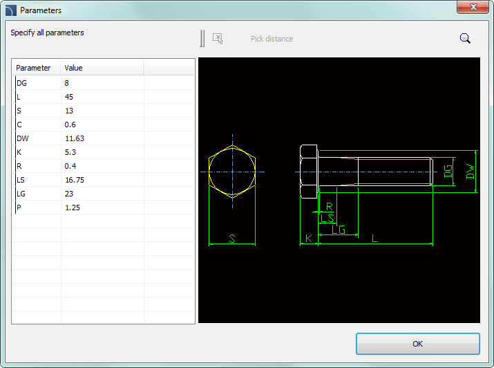
Specify all parameters – insertion of selected object with the possibility to specify all editable parameters. Selecting this option and pressing the OK button will open a new Parameters window.
The Parameters dialog window
allows to specify the values of each parameter. It is also possible to specify
dimensions directly from the drawing. In such case user has to activate the
dimension field and press the Pick distance  button.

Parameters dialog window
Hint
Selected object data is displayed as the default data in the „Parameters” dialog window.
Procedures
1. Run the Standardized parts command.
2. In the dialog window select the needed object category. After that the element preview will be displayed and on the detailed list you will be able to see all available element types and sizes.
3. (Optional) If the list of available types possesses subcategories double click on a category will expand it and you will be able to see its content.
4. (Optional) Right click on any item and from the menu choose the Expand all/Collapse all option.
5. Choose the needed element form the detailed list.
6. (Optional) Change the View for the selected element.
7. (Optional) Change the settings for the Object style options.
8. (Optional) Select the Enter all dimensions option to specify inserted objects dimensions.
9. Click the OK button to insert selected object into the drawing.
10. Specify the insertion point.
11. Specify the object rotation angle.
12. After inserting the block user can adjust its length with a specified type of series. Click the red support line in order to change the length or press the Enter/Esc to accept the current size.

Inserting standardized parts to the drawing
The way how to insert selected symbols into the drawing depend on its type and the chosen view. Inserting objects, which dimensions are determined on the basis of types of series only need to select the insertion point (P1) and specify the rotation angle (P2).

During insertion of objects such as: holes (transitional, threaded), drills, screw joints, rivets and others user should specify an additional parameter - most often the element length (e.g. the dimension that determine the hole depth or the connection thickness).
Normally user should specify the (P1) point, and afterwards another point that at the same time define the object's length or other dimension (P2). This point will also determine the insertion angle.

This parameter can be also specified by using the Enter all dimensions option. After specifying all dimensions in the dialog window, user should insert the object by indicating the insertion point (P1) and the rotation angle (P2).
Screw connections
The Standardized parts command allows to insert connections(simultaneously insertion of a screw and a nut) in three most commonly used variants:
•hexagon head bolt + nut,
•countersink + hexagon socket head cap screw and nut,
•hexagon socket head cap screw + nut.
In order to insert a screw connection user should select the appropriate connection type and the screw size in the dialog window. Afterwards he should indicate on the drawing the insertion point (P1) and the connection thickness (P2).
For screw connections program controls the minimum and
maximum connection length for the selected screw type and places a nut only in
the thread length. Because of that, in connections it is necessary to select the
appropriate screw length.
A mistake would be to insert for example a screw
with a 30 mm length for a connection that has got a 40 mm thickness.
|
|
Screw too short |
Correct screw length |
Screw with too |
|
|
| ||||
The Quick edit) command allows dynamic lengthening or shortening of some standardized elements. For example: if in the drawing a M8 x 55 screw from the PN EN 24016 standard is inserted, then it can be lengthened or shortened to the length of 40 to 80 mm according to the elements contained in the specified standard.
 |
Example of a quick edition length change.
|
Notice The disappearance of one of
the tags means reaching the limit of the given types of series
length. |
After selecting the Quick edit command and indicating the object, arrows that symbolize the object enlargement and reduction will be visible. Clicking on the symbol will display temporary red support lines, suggesting the user that he can change the dimensions of selected type of series. Clicking on one of these lines will change the object into a bigger/smaller.

Procedures
1.
Run the Quick edit  command.
2. Indicate an object that was inserted with the Standardized parts command.
3.
Edit an object by clicking on the lengt edit  arrows symbol.
4. By clicking on the support line select a new length from the available type of series.