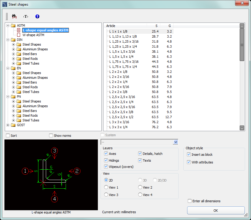
The Steel shapes command allows user to insert to the project all kind of steel shapes such as: flat bars, L-shapes, U-shapes, Z-shapes etc. For all objects databases with many national and international standards including: PN, EN, DIN and ANSI are available.
Steel shapes have got their own mass unit defined. Thanks to this it is possible to obtain information about length and mass of elements inserted into the drawing. It is also possible to automatically obtain the full BOM of steel (or other materials).
Most steel shapes available in CADprofi program are steel elements. Thanks to the possibility to specify all dimensions it is possible to insert custom profiles such as aluminum, copper and others. If custom profiles are being inserted then it is necessary to adjust the type, material kind and unit mass or the total mass of inserted elements. The easiest way to adjust these parameters is to use the Attributes and descriptions command which allow to simultaneously change the data for multiple objects (check page 37).

Steel shapes dialog window
Options used in this dialog window have been described in previous chapters (check page 369).
Steel shapes available in the library have got the possibility to be inserted in a main view or in additional views. These views are indicated in the preview window with arrows.
For some views, hiding lines are included. With the help of the Object style option it is possible to enable or disable the creation of invisible lines in the inserted object.

|
Main view |
Side view |
Top view |
Procedures
1.
Run the Steel shapes  command.
2. In the dialog window select the needed object category. After that the element preview will be displayed and on the detailed list you will be able to see all available element types and sizes.
3. (Optional) If the list of available types possesses subcategories double click on a category will expand it and you will be able to see its content.
4. (Optional) Right click on any item and from the menu choose the Expand all/Collapse all option.
5. Choose the needed element form the detailed list.
6. (Optional) Change the View for the selected element.
7. (Optional) Change the settings for the Object style options.
8. (Optional) Select the Enter all dimensions option to specify inserted objects dimensions.
9. Click the OK button to insert selected object into the drawing.
10. (Optional) If you decide to insert a view from the top, then in the Parameters window specify the select steel shape length (it is necessary to later create correct BOMs).
11. Specify the insertion point on the drawing.
12. If you decide to insert the main view specify the rotation angle. For other views, indicate the second point thanks to which you will determine the steel shape length.

Examples of drawing with inserted steel shapes
Steel profiles are inserted as blocks. X scale for side views correspond to the profiles length. In case of cross-sections (main views), the profile length corresponds to the block Z scale. Thanks to this by changing the scale (X or Z) in the properties window it is possible to adjust the profile length after inserting them into the drawing.
|
| ||||
|
Closed profile with 400 mm length. |
Changing the profile length to 500 mm, | |||
|
Hint To display the properties window in CADprofi program, user should press the CTRL + 1 or select the appropriate command from the CAD program top menu. |
 Steel shapes and metallurgical
products