|
|
|
|
|
Threaded piping system example |
Copper piping system example |
Polypropylene piping system example |
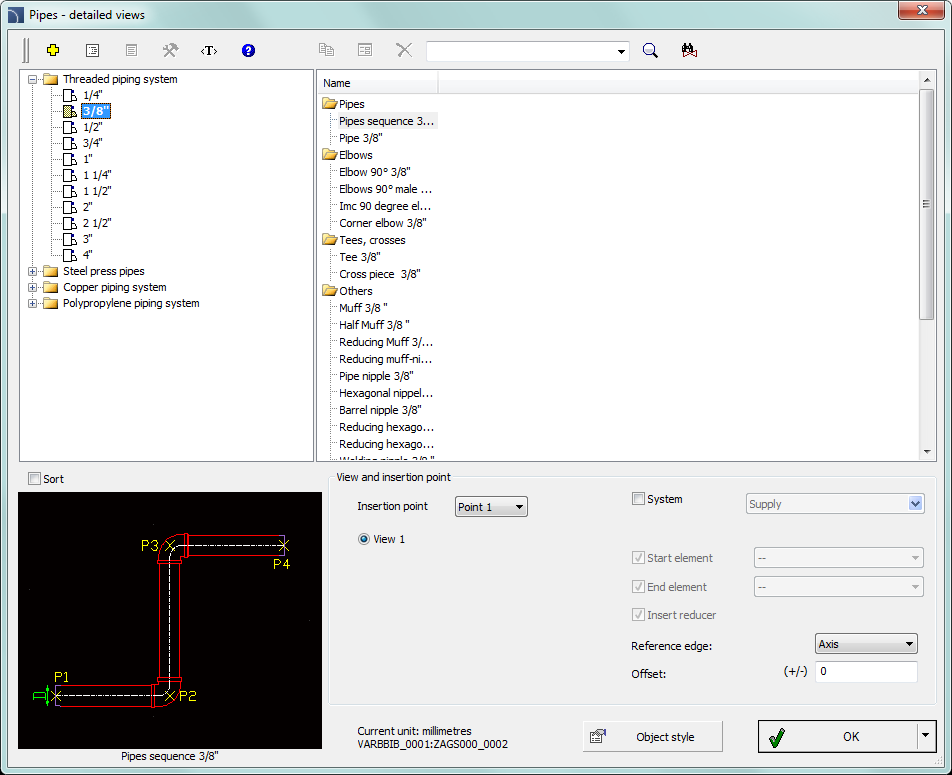
This command contains detailed views for threaded, pressed, copper and plastic pipes. In the current program version the data layout has changed. The current data layout is prepared in accordance to the size of pipes, thank to which it is a lot easier to design the installation with a certain diameter, as well as, it is possible to automatically join pipes with elbows and tees.
A system of pressed pipes and fittings for steel pipes which allows for convenient drawing of installations with automatic insertion of appropriate elbows (12 - 108 mm) has been added to the program. In addition, a possibility to connect this system with other installations (by using the threaded or flanged fittings) has been added to the program.
|
|
|
|
|
Threaded piping system example |
Copper piping system example |
Polypropylene piping system example |
User has the possibility to insert single objects and to draw whole sequences of pipes with automatic insertion of appropriate elbows.
|
|
|
|
Sequence with 90˚ elbows |
Sequence with 45˚ elbows |
When drawing sequences only elbows that are available in the database are being inserted. Because of that it may happen that the program will correct the length of inserted pipe sections in such a way that it will be possible to draw it with standard elbows (mostly, only 45° and 90° elbows are available).
Correction of pipe sections when indicating consecutive points:


Graphical layout and the base dialog window functions used for drawing pipe systems is the same as in the Parametrical armature dialog window.
|
Draw along "infoline" - an option allowing instant drawing of pipes along any designated polyline/polylines or line string/strings. |
|
6 Procedures
1.
Run the Pipes - detailed views  command.
2. In the dialog window select the appropriate category and fitting size (diameter).
3. (Optional) If a list has got subcategories, double click on a particular subcategory in order to expand it and view its contents.
4. (Optional) Change the View for the selected fitting.
5. (Optional) Change the settings for the Object style.
6. (Optional) Enable the System option and select the installation type.
7. Click the OK button in order to insert the selected fitting in the drawing.
8.
(Optional) Click the  button and
select Insert (specify all dimensions), in order to
specify the dimensions of inserted object.
9.
(Optional) Click the  button and
select Insert (specify style for object), in order
to make changes in the Object style before
inserting an object.
10. Click on the edge of the line or fitting in order to attach the selected fitting.
11. (Optional) Click at any point in the drawing in order to insert an element.
12. Specify the rotation angle and the insertion direction.
1.
Run the Pipes - detailed views  command.
2. In the dialog window select the Sequence of pipes position.
3. (Optional) Enable the System option and select the installation type.
4. Click the OK button in order to start drawing line sequences by indicating consecutive points.